A numerical simulation of the D.C. continuous casting process including nucleate boiling heat transfer
- PDF / 991,701 Bytes
- 10 Pages / 597.28 x 785 pts Page_size
- 78 Downloads / 351 Views
I.
INTRODUCTION
MOULD LINER --------i
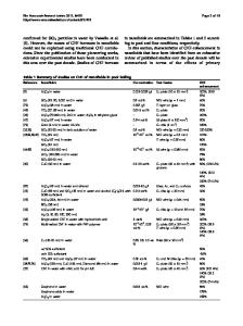
SINCE the commercial viability of the direct-chill (D. C.) continuous casting process was established in the 1930's, it has been used most extensively by the nonferrous metal industry. Following the first significant attempt by Roth ~ in 1943 to model mathematically the thermal problem associated with the process, numerous analytical 2"3"4 and numerical 5-14 models of ever increasing sophistication have been proposed. The final accuracy and generality of the proposed numerical models following that of Adenis et al 6 have generally not been limited by their ability to solve the nonlinear governing equation with the associated free surface problem at the solid-liquid interface, but by the simplifying assumptions regarding the external boundary conditions. In this work, an existing numerical Finite Element Method (FEM) model of the D. C. continuous casting process 9 is used in conjunction with experimental data from three A6063 AI alloy cylindrical ingots to develop a method of calculating the cooling conditions in the submold or secondary cooling region of the ingot. The method is applicable in the simulation of ingots whose secondary cooling is by heat transfer to a free falling film of water on the surface of the ingot.
II.
T H E EXPERIMENTAL DATA
Solid-liquid interface profiles and temperatures within the solidifying ingot were obtained from three 0.1524 m diameter A6063 A1-Mg alloy ingots cast at 1.69 x 10⁻³, 2.54 x 10 -3, and 3.81 x 10 -3 m per second. These experimental data were taken when the ingots had reached steadystate casting conditions. The casting configuration was a typical hot-top D. C. continuous casting mold as illustrated in Figure 1. The aluminum mold had an insulating mold liner and, for primary cooling, an internal cooling manifold. For secondary cooling of the ingot, the primary cooling water was jetted out the bottom of the mold to impinge D. C, WECKMAN, Graduate Student, and P. NIESSEN, Professor, are both with the Department of Mechanical Engineering, University of Waterloo, Waterloo, Ontario, Canada, N2L 3G1. Manuscript submitted January 29, 1982. METALLURGICAL TRANSACTIONS B
,I
LAUNDER --~ .,...,,,,.,~ j......~ ~
~
5v,
D
LSECONDARYCOOLING WATER SPRAY
SOLID
1.
q.
//----STARTER BLOCK
Fig. 1 - - Schematic diagram of the D. C. semicontinuous casting process in cylindrical coordinates.
directly on the emerging surface of the casting. The initial cooling water temperature was constant at 283 K, and the flow rate was 1.89 x 10.3 m 3 per second. In addition, for all three casting runs, the pouring temperature of the liquid metal was 963 K. To delineate the shape of the solid-liquid interface, a liquid AI-Zn alloy was poured into the sump. The liquid AI-Zn alloy was at the same temperature as the A6063 A1 pouring temperature, and the turbulence induced in the liquid metal by the open-pouring operation assured very rapid distribution of the liquid AI-Zn alloy throughout the sump. Subsequent sectioning, polishing, and etching of the solidified
Data Loading...