A Scanning-Probe Technique for Mapping the Hardness of Lead-Free Solders
- PDF / 3,471,495 Bytes
- 5 Pages / 612 x 792 pts (letter) Page_size
- 71 Downloads / 275 Views
A Scanning-Probe Technique for Mapping the Hardness of Lead-Free Solders Jennifer L. Hay1, Carlos Morillo2, and Julie Silk3 1
Nano-Scale Sciences Division, Agilent Technologies, 105 Meco Lane, Suite 200, Oak Ridge, TN 37830, U.S.A. 2 Center for Advanced Life Cycle Engineering (CALCE), University of Maryland, College Park, MD, 20142, U.S.A. 3 Electronics Measurement Group, Agilent Technologies, 1400 Fountaingrove Pkwy, MS 1USF, Santa Rosa, CA, 75403, U.S.A.
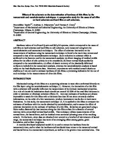
ABSTRACT A rapid nano-indentation measurement technique is employed to produce surface maps of hardness. Each indentation cycle requires less than three seconds, including surface approach, contact detection, force application, withdrawal, and movement to the next indentation site. Traditional nano-indentation analyses are applied to the force-displacement measurements from each indentation, but information storage and presentation owe much to scanning-probe technology. Consequently, this nano-indentation technique produces three-dimensional images of mechanical properties which are stored and manipulated just like scanned images. In the present work, we use this technique to map the hardness of a SAC 305 solder joint with gold plating. After extended isothermal aging, the solder joint comprises three constituents: a tin-rich matrix, a bulk intermetallic AuSn4, and an interfacial intermetallic (Cu, Ni, Au)6Sn5. The softest material is the tin-rich matrix, which has a hardness of 0.51±0.07 GPa. The hardness of the bulk intermetallic is 2.12±0.18 GPa. The interfacial intermetallic has extraordinary hardness— greater than 8 GPa. Under uniform plastic strain, the mismatch in hardness between the interfacial intermetallic and surrounding material may increase the local stress intensity factor which drives interfacial fracture. INTRODUCTION The reliability of soldered connections in electronic packaging depends on mechanical integrity, because mechanical failure can cause electrical failure. Mechanical integrity, in turn, depends on mechanical properties. Thus, the purpose of this work was to quantitatively map the mechanical properties of all the components of a solder joint. We focus specifically on the SAC 305 solder alloy (96.5% Sn, 3% Ag, and 0.5% Cu) due to its prevalent use in electronic packaging. Generally, soldered joints are not uniform. They have a complex microstructure which depends on many factors: the solder and plating materials, the size of the joint (which constrains grain size), and the exposure of the joint to stress and temperature over time. Some alloys favor the development of intermetallic compounds (IMCs) within a tin-rich matrix.
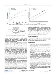
In soldered joints, IMC development depends, in part, on the metallization used to prepare components for bonding. Copper is typically used for board and electronic terminals. Commonly, a barrier layer of nickel is applied to the copper, followed by a gold layer that protects the nickel and improves wetting. In such bonds, AuSn4 forms in the bulk and migrates to the solder joint interface with time to form a britt
Data Loading...