Aqueous slurry erosion in some cobalt base superalloys
- PDF / 1,662,861 Bytes
- 5 Pages / 613 x 788.28 pts Page_size
- 60 Downloads / 260 Views
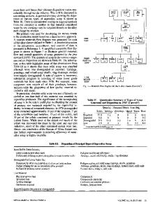
were p e r f o r m e d with a c o n s t a n t flow r a t e of 40 gallons p e r h (176 l i t e r s per h). D i s c - l i k e s a m p l e s , Fig. 2, were e l e c t r i c - d i s c h a r g e m a c h i n e d (EDM) f r o m plate and rod s t o c k u s i n g a
VPRESSURE
ACCUMULATOR ~ ( 17OO psi ) ~ (ll."f M Pa) - - ~
GAGE ( 0 - 3OOO psi ) ( O - 2 0 . 7 MPc)
~ \
RELIEF O| u-/
r
' "RRY
2000psi ) ( 13B MPo) SUCTION
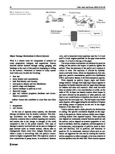
Fig. 1--Schematic drawin of the system used in the study of erosion of materials by aqueous silica slurries. '
/. , ~ 0 . 7 0 0 "
Dic. 0.018 m. )
EXPERIMENTAL The s y s t e m developed for this t e s t is shown schem a t i c a l l y in F i g . 1. An aqueous a b r a s i v e s l u r r y was pumped by a b a l l - c h e c k valve m e t e r i n g pump fitted with t u n g s t e n c a r b i d e b a l l s . The pump has a c o n t i n u ously a d j u s t a b l e flow up to 40 gallons p e r h (176 l i t e r s per h) and is capable of m a i n t a i n i n g p r e s s u r e s in exc e s s of 2000 p s i (13.8 MPa). The p r e s s u r e was indicated by a c a l i b r a t e d 0 to 3000 psi (0 to 20.7 MPa) p r e s s u r e gage with 25 psi (0.172 MPa) d i v i s i o n s . An a c c u m u l a t o r was placed in the high p r e s s u r e side to e l i m i n a t e p u l s i n g in the high p r e s s u r e fluid. The s l u r r y used was a 30 pct solids by weight of 4.5 pm c r u s h e d s i l i c a sand in d i s t i l l e d w a t e r . A l l t e s t s A. E. MILLER and J. P. COYLE are Professor and Project Engineer, respectively, Department of MetallurgicalEngineeringand Materials Science, University of Notre Dame, Notre Dame, IN 46556. Manuscript submitted October 24, 1977.
METALLURGICALTRANSACTIONSA
RUBBER WASHER 9. .-
o ozs"
9 ~I (0.000064m.1
I'~~176
~
,
'
I~]
I
SAMPLE RETAINER SEAT
(0.011m. )
~_ ~_
(b)
TEST VALVE
0.I00" ( O.OO25 rn')
Fig. 2--Schematic of valve assembly and test sample.
ISSN 0360-2133/78/1211-1777500.75/0 9 1978AMERICANSOCIETYFOR METALSAND THE METALLURGICALSOCIETYOF AIME
VOLUME9A, DECEMBER 1978-1777
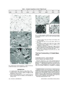
Table I Composition and Processing of Stellite Cobalt Base Alloys Tested in the Orifice Erosion Studies Nominal Chemical Composition, Pct Alloy, Heat
Ni
Co
Cr
Mo
W
Fe
Si
Mn
C
B
Processing
Stellite 6KC (B625)
3.0*
Bal.
30
1.5"
4.5
3.0*
2.0*
2.0*
1.85
-
Stellite 6KC (3147)
3.0*
Bal.
30
1.5"
4.5
3.0*
2.0*
2.0*
1.53
-
Stellite Stellite Stellite Stellite Stellite
3.0* 3.0* 3.0" 3.0* 3.0*
Bal. Bal. Bal. Bal. Bal.
30
30 30 29 31
1.5" 1.5" 1.5* 1.5* -
4.5 4.5 4.5 4.5 12.5
3.O* 3.0* 3.0* 3.0* 3.0*
2.0* 2.0* 2.0* 1.5" 1.0"
2.0* 2.0* 2.0* 1.0" 1.0"
1.6 1.6 1.2 1.1 2.3
1.0" 1.0"
Hot rolled from a powder compress Hot rolled from a powder compress Wrought Wrought Wrought (P/M) (P/M)
6K (I000) 6K 6B 6 3
*Maximum.
b r a s s tube e l e c t r o d e . The d i s c s were then s u r f a c e ground to the p r o p e r t h i c k n e s s and an o r i f i c e was s p a r k m a c h i n e d through the d i s c s . A 0.020 in. (0.00051 m) d i a m t u n g s t e n wire was
Data Loading...