Asperity Creep Under Constant Displacement
The main tool in this manuscript is the Finite Element simulation of creep in asperities, which are modeled as elastic-perfectly plastic (i.e. no hardening rule in addition to the creep laws) hemispheres in contact with a rigid flat. A large number of sim
- PDF / 819,785 Bytes
- 23 Pages / 439.36 x 666.15 pts Page_size
- 71 Downloads / 332 Views
Asperity Creep Under Constant Displacement
As pointed out in Chap. 1.1, the behavior of an elastic-perfectly plastic hemisphere in contact with a rigid plane has received a great deal of interest. Many recent efforts used the method of Finite Element modeling, from which empirical laws of the behavior were extracted. In this chapter, an analysis of the transient creep behavior of an asperity is presented. The aim is to gain a fundamental understanding of the root cause of transient effects in friction by investigating the creep behavior of the individual junction. This study restricts itself to the stress relaxation process of an asperity at a fixed interference. For an analysis of the behavior of an asperity under the—more complicated—constant force boundary condition, see Chap. 3. It is further assumed that the asperity is in the fully plastic contact regime. The term fully plastic is used here in accordance with Kogut and Etsion[82, 128], meaning that everywhere along the contact line the material has reached the yield stress. Earlier studies on the influence of creep on the contact of a sphere and a flat focused on the complementary problem of a rigid sphere indenting an elastoplastic flat [41, 172, 179, 187, 207]. The specific aim of these studies was often to derive or test a constitutive material creep law from a measured indentor response. In recent years, new applications for nano-indentation of polymers or biological tissue have invigorated the field. The problem was studied both empirically, e.g. by Mulhearn and Tabor [172], as well as analytically, e.g. by Bower et al. [41] or by Finite Element simulations, e.g. by Ogbonna et al.[179]. However, because the problem studied by these authors is complementary to the one studied here, it shows a fundamentally different behavior. During the revision of [100], the author became aware of the recent publication [49] by Brot et al., who independently have presented an FEA study on creep in asperities. While their approach is very similar to the one presented here, their study focused on a different set of boundary conditions, assuming constant force instead of constant displacement of the contacting flat. Also, Brot et al. [49] have used a power law instead of an exponential material creep law. The organization of this chapter is as follows: in Sect. 2.1, the setup of the Finite Element simulation is described, including the material laws used for modeling the creep behavior. Section 2.2 discusses the simulation results. Section 2.2.1 focuses A. Goedecke, Transient Effects in Friction, Engineering Materials, DOI 10.1007/978-3-7091-1506-0 2, © Springer-Verlag Wien 2013
17
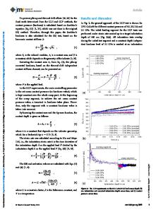
18 Fig. 2.1 (a) Sketch of the geometry. (b) The Finite Element mesh used for the simulation
2 Asperity Creep Under Constant Displacement
a
b
on a comparison of the relevant aspects of asperity evolution known from previous research to the present simulation. In the following Sect. 2.2.2, an overview of the new simulation results of the creep behavior of an asperity is given. In Sects. 2.2
Data Loading...