Atypical Defects in a B2 Fe-40Al-0.7C-0.5B Alloy
- PDF / 3,549,347 Bytes
- 6 Pages / 411.66 x 640.98 pts Page_size
- 78 Downloads / 301 Views
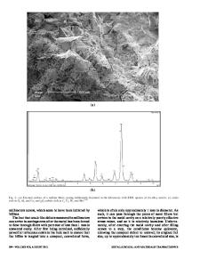
Fig. 1. Z-contrast image of the planar faults. The bright spots corresponds to Fe atoms while the weaker spots corresponds to Al atoms. The foil normal is [001] and the incident electron beam is also [001]. Three variants (A, B and C) of the fault are seen lying edge- on with the displacement vector for A = 1/2[010], and for B and C = 1/2[001]. intermediate cooling rate such as air-cooling in the presence of boron. The detailed structure of the 1001) complex fault was studied by both diffraction contrast analysis and by using the Z-contrast tech-
nique [17]. It was shown in that study that the fault had an in-plane displacment vector characterized by 1/2 and that it was possible to have six variants of the fault, two per cube plane. It was also found that one layer of aluminum was missing at the fault plane. These features can be readily seen in the Z-contrast image reproduced in Figure 1.The bright field TEM image (Figure 2) shows five of the six variants of the (0011 fault. It was speculated that boron may have segregated to the fault and lowered the fault energy. In this paper, we report the results of further investigation of this alloy and the effect that boron has on the dislocation structure following different heat treatments. EXPERIMENTAL PROCEDURE The defect structures in a binary Fe-40A1 alloy and a quaternary Fe-40A1-0.5B-0.7C alloy are
compared in this investigation (in the rest of this paper we refer to the binary alloy as FeAl and the quaternary alloy as FeA1BC). Where relevant, we draw comparisons to the defect structure in a ternary Fe40A1-0.6C alloy to isolate the effect of boron addition versus carbon addition, but it should be noted that the microstructural evolution and mechanical properties of the ternary alloy have been published in detail elsewhere [18,19]. The FeA1BC alloy was made by induction melting followed by hot extrusion at 1000°C with an extrusion ratio of 16:1. The FeAl alloy was provided by Dr. C.T. Liu of Oak Ridge
National Laboratory. Microstructures in the extruded, quenched, and in the quenched and subsequently aged conditions were examined by TEM. Foils for transmission electron microscope examination were prepared by jet polishing 3-mm disks with an electrolyte of 20% HNO 3 in methanol at -26°C and observed in a Philips 420 transmission electron microscope (TEM) operating at 120 KV. Dislocations KK4.5.2
Fig. 2. TEM micrograph showing five distinguishable variants of the {001} faults using g=110. Different variants are labeled a, a', b, b' and c. a and a' are parallel to the X direction, b and b' to the Y direction and c to the Z direction. a and a' are on the same plane, b and b' are on the same plane. a, b and c are in contrast while a' and b' exhibit only residual contrast. and faults were characterized in bright field and weak beam dark field mode using the conventional gob type contrast analysis to determine the Burgers vector, b, of the dislocations and the displacement vector R of the faults. Line direction of the dislocations were obtained by stereographic projec
Data Loading...