Automated Planar Patch-Clamp
Ion channels are integral membrane proteins that regulate the flow of ions across the plasma membrane and the membranes of intracellular organelles of both excitable and non-excitable cells. Ion channels are vital to a wide variety of biological processes
- PDF / 435,182 Bytes
- 17 Pages / 504.57 x 720 pts Page_size
- 99 Downloads / 300 Views
r (ed.), Ion Channels: Methods and Protocols, Methods in Molecular Biology, vol. 998, DOI 10.1007/978-1-62703-351-0_13, © Springer Science+Business Media, LLC 2013
171
172
1
Carol J. Milligan and Clemens Möller
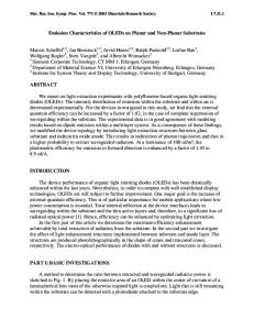
Introduction The well established patch-clamp technique developed by Erwin Neher and Bert Sakmann (1) involves the manual positioning of a glass microelectrode onto the surface of a single cell. A seal is formed, and with the application of a small amount of negative pressure (or a voltage pulse), the cell membrane at the tip of the pipette (the patch) ruptures allowing direct access to the interior of the cell, enabling control of the membrane voltage. Here we describe the automated planar patch-clamp approach using the platform Patchliner as an example (Fig. 1a). This approach requires the manual preparation of the cells in suspension, and because capturing cells is a random process it is vital that they are of extremely high quality with uniform homogeneity. The automated planar approach involves the robotic delivery of solutions, cells, and compounds onto the planar chip (Fig. 1b–d), which is a tiny borosilicate sheet of glass with a micron-sized aperture in the center.
Fig. 1 (a) The automated planar patch-clamp platform consists of the NPC-16 Patchliner, amplifiers, and a computer. It has a much smaller foot print compared to a conventional rig. The Patchliner takes up to three NPC-16 chips per session. (b) Image of part of the NPC-16 multi-well microfluidic cartridge with a solution delivery pipette inserted into the extracellular inlet of one chamber. Waste chamber highlighted by ** and intracellular chamber highlighted by *. (c) Image of the underside of the cartridge in which the intracellular solution compartments are highlighted with dye. (d) Schematic of a single chamber showing the arrangement of extracellular, intracellular, and waste chambers as well as the position of the planar chip
Planar Patch-Clamp
173
Chips are embedded in microfluidic chambers within a chip cartridge (Fig. 1d). The aperture in the chip is the equivalent of the pipette tip in the conventional method. There are 16 individual chips within a single cartridge and 8 of these are used simultaneously for each experiment. Once the solutions and cells have been robotically delivered into the microfluidic chambers, negative pressure is applied from below each chamber independently, to attract a single cell onto each chips aperture. Further application of negative pressure ruptures the membrane sitting over the aperture, establishing the whole-cell configuration. The exchange of external solution for both manual and automated methods is relatively straightforward. However, the exchange of intracellular solution is significantly easier with Patchliner, where it is a routine feature. Apart from manual preparation of the cells, solutions and compounds, the whole process is controlled by preprogrammed computerized protocols in PatchControlHT, resulting in routine reproducible comparable data output. Another versatile feature
Data Loading...