Cold model study of the surface profile in a continuous slab casting mold: Effect of second phase
- PDF / 340,067 Bytes
- 3 Pages / 612 x 792 pts (letter) Page_size
- 13 Downloads / 353 Views
~s,~,/~..o~, = ~2/tz,
p.~/p~o,~,=
p2/p,
[l]
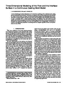
[V22 - V,Z]/2g = A, (1 - Po/Pw)
[2]
where Vt and Vz are the velocities normal to planes l and 2, respectively; g is the acceleration due to gravity; A~ is the wave amplitude of the meniscus in the presence of the second phase; and Po and pw are the densities of the oil and salt solution, respectively. When second phase is not present, Po is zero and Eq. [3] simplifies to
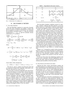
where/z i and Pi are the viscosity and density of the/th phase and the subscripts 1 and 2 refer to the liquids used in the model to simulate the metal and slag phases, respectively. The viscosity and density of the slag phase depend on the composition of casting powder and its temperature. At the slag-metal interface, its temperature is expected to be close to that of liquid steel, but its top face which is exposed to atmosphere will be at a much lower temperature. Besides, the temperature of the slag-metal interface also is not constant. So, Eq. [1] cannot be exactly satisfied by the cold model. However, if the average temperature of the flux is assumed to be 1300 ~ the ratio of viscosities of slag to metal is 15 or more. v~ The density ratio of slag to metal is only about 0.375. But the density ratios of commonly used simulating liquids, i.e., oil for the slag and aqueous phases for metal, are much higher than this value. Therefore, it is difficult to simulate the actual slag-metal system using cold models. The experiments were carried out to understand the twophase behavior using oils and a commercial grade zinc chloride solution over a wide range of viscosity and density ratios. Table I gives the relevant physical properties of the oils and salt solutions used for the present experiment and that of the slag and the liquid steel. The molds used in the present investigation were made up of Perspex glass. The details of the mold and the nozzle configuration were discussed in our earlier work. t61The experimental conditions and the nozzle details are given in Table II. Experiments were recorded using a TV camera
DR. DHARMENDRA GUPTA, formerly Research Scholar, Centre for Advanced Study, Department of Metallurgy, Indian Institute of Science, is Assistant Manager, Jindal Vijayanagar Steel Ltd., Bangalore 560 001, India. PROFESSOR A.K. LAHIRI is with the Centre for Advanced Study, Department of Metallurgy, Indian Institute of Science, Bangalore 560 012, India. Manuscript submitted November 14, 1994. METALLURGICALAND MATERIALSTRANSACTIONSB
from the front side of the mold. The recorded images were analyzed using an image analyzer (DT-IRIS 2851). Figures l(a) and (b) show one-half of the meniscus profile, without and with second phase, under identical operating condition. It can be noticed from the figures that the meniscus is wavy with a crest and a trough. The meniscus was not stationary and it fluctuated with time. Thereby, the locations of the crest and the trough and the vertical distance between them, shown as A~ in Figure 2, varied with time. For convenience of discussion, the maximum vertical d
Data Loading...