Deformation of Experimental Fuel Pins with Improved Zirconium-Alloy Cladding in Reactor Tests
- PDF / 529,204 Bytes
- 5 Pages / 594 x 792 pts Page_size
- 65 Downloads / 308 Views
DEFORMATION OF EXPERIMENTAL FUEL PINS WITH IMPROVED ZIRCONIUM-ALLOY CLADDING IN REACTOR TESTS A. V. Burukin,1 A. I. Dolgov,1 A. L. Izhutov,1 P. A. Il’in,1 V. V. Kalygin,1 M. A. Mokeichev,1 A. V. Ugryumov,2 and Yu. N. Dolgov2
UDC 621.039.548
A stand for inspecting experimental fuel pins in the cooling pool of the MIR.M1 reactor and methodological approaches to measuring the height and diameter of experimental fuel pins are described. The basic characteristics of the equipment used for performing measurements are described. The structural features of an experimental FA (EFA) and the test parameters of experimental fuel pins in an assembly in one of the loop facilities of the MIR reactor are presented. The results of a series of measurements of the diameter and height of irradiated fuel pins with cladding made from different zirconium alloys with different average fuel burnup over the EFA are shown.
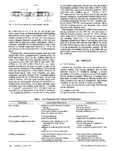
New cladding materials are being developed in order to improve the reliability and competitiveness of the fuel pins used in water moderated and cooled power reactors, specifically, zirconium alloys that will impart greater corrosion resistance and less deformation during operation. The change in the dimensions of fuel pins under irradiation has been studied in post-reactor studies of experimental fuel pins irradiated in research reactors and full-scale fuel pins extracted from standard FA [1–3]. However, such data characterize only the final state of a fuel pin. It is necessary to know the geometric parameters during operation in order to obtain a deep understanding of the dependence of deformation of a fuel pin on fuel burnup. Periodic measurements of the length and diameter of standard fuel pins on NPP inspection are impossible to make because the refueling time and scheduled preventative maintenance are strictly regulated, so that such studies are usually conducted when testing fuel pins as part of experimental FA in research reactors. Experimental fuel pins were tested in a loop facility of the MIR reactor under conditions simulating standard FA operation with intermediate studies conducted on an inspection stand placed in a cooling pool [4, 5]. The testing program included visual inspection of fuel pins and elements of FA, measurements of cladding diameter and height of fuel pins in the outer row using a special radiation-resistant TV camera and a special measuring module. This made it possible to obtain data on the change in the diameter and height of experimental fuel pins under irradiation to average burnup ~32 MW·days/kg. The design of the inspection stand is shown in Fig. 1. A measurement module, or TV camera, is mounted on an X–Y table for measuring the diameter and making visual inspections of fuel pins. This module together with the table drives makes it possible to aim a sensor on the test fuel pin and to position the sensor relative to the surface of the fuel pin. The movement of the table in the horizontal plane and the rotation of FA are conducted with the aid of submersible stepping motors. The angle o
Data Loading...