Development of Computational Models for Coiling Process with the Belt Wrapper
- PDF / 907,125 Bytes
- 6 Pages / 593.972 x 792 pts Page_size
- 81 Downloads / 390 Views
l is coiled by a mandrel, pinch rollers, grooved joint, belt wrapper, and motor, and its coiling amount and type are determined by a customer or engineering requirement in the steel industry. Coiling methods can be classified by how the end of the strip is connected to the rotor, but the inner part of the coil generally takes more pressure than the outer part of the coil due to the pressure YONGHUI PARK, Ph.D Candidate, and HYUNCHUL PARK, Professor, are with the Graduate School of Engineering Masterships, Pohang University of Science and Technology (POSTECH), San31, Hyoja-dong, Nam-gu, Pohang Kyungbuk 790-784, Republic of Korea. Contact e-mail: [email protected] Manuscript submitted April 16, 2016. Article published online July 6, 2016. METALLURGICAL AND MATERIALS TRANSACTIONS B
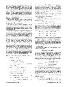
accumulation by coiling tension T.[1,2] If coiling layer exceeds its limit, the sleeve and inner part of the coil will be deformed first. Even though coiling process that uses a grooved joint that fixes the end of the strip directly on the rotor; the sleeve has been researched about stress distribution,[3,4] residual stress of stainless steel,[5] coil slumping,[6] and coiling tension control,[7–9] but coiling process uses a belt wrapper had not been investigated before. Because this activity needs many computations by using finite element method to calculate slip of the strip coil and computational model is hard to be defined about nonlinear behaviors of rubber and contact layer, so experiential manual has been effective in a real coiling operation. To understand coiling mechanism in detail, this paper establishes finite element (FE) model and analytical model for coiling process using a belt wrapper that is known as strip head end positioning on a free tension reel and that has been studied before, and gives physical means by comparing pressure and stress distributions. FE model includes several coiling stages: (1) coiling the strip on the sleeve by the belt wrapper without coiling tension T, (2) applying T on the opposite side of the strip without the belt wrapper, and (3) rotating the sleeve and strip coil with T. By using two models, pressure distributions according to elasticity of the belt wrapper E and frictional force comparison on the outmost of the sleeve were suggested to explain how the strip coil comes united. Lastly, radial stress on the sleeve was compared between coiling with the belt wrapper and coiling with the grooved joint to show trend of stress distribution. Coiling process consists of the sleeve, the strip, and the belt wrapper (Figure 1).[1] The process is classified into three stages. First, the strip is coiled around the sleeve with compression from the belt wrapper. The strip is free without coiling tension T. Generally, the sleeve turns two or three rotations to give frictional force among contact layers. In this model, the sleeve turned about 2.125 rotations. The friction that can be applied among contact layers increases as the number of rotation increases. When the sleeve is stopped, T is applied to the opposit
Data Loading...