Effect of Hydrostatic Pressure on Indentation Modulus
- PDF / 747,292 Bytes
- 6 Pages / 612 x 792 pts (letter) Page_size
- 10 Downloads / 531 Views
1049-AA02-09
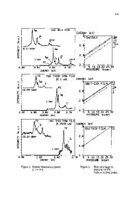
Effect of Hydrostatic Pressure on Indentation Modulus W. M. Mook, and W. W. Gerberich University of Minnesota, Minneapolis, MN, 55455 ABSTRACT The high pressures generated at a contact during nanoindentation have a quantifiable effect on the measured indentation modulus. This effect can be accounted for by invoking a Murnaghan equation of state-based analysis where the measured indentation modulus is a function of the hydrostatic component of the stress state which is generated beneath the indenter tip. This approach has implications pertinent to a range of mechanical characterization techniques that include instrumented indentation and quantitative atomic force microscopy (AFM) since these techniques traditionally consider only zero-pressure modulus values during data interpretation. To demonstrate the validity of this approach, the indentation modulus of four materials (fused quartz, sapphire, rutile and silicon) is evaluated using a 1 µm radius conospherical diamond tip to maximum contact depths of 30 nm. The tip area function is independently determined via AFM while the unloading stiffness from the load-displacement data is determined using standard Oliver-Pharr analysis. INTRODUCTION Nanoindentation has become one of the most widely used characterization techniques for quantifying the mechanical properties of thin films and freestanding structures [1, 2] at length scales below 1 µm. The method most often employed for nanoindentation data analysis is that of Oliver and Pharr (OP) [3]. This technique assumes that the initial point of unloading is purely elastic. Thus the initial slope of the load-displacement data is the elastic stiffness, S , and is defined by 2 (1) S=β Er A π where β is a dimensionless parameter, A is the projected area of contact and Er is the reduced modulus of the tip-substrate system. The reduced modulus is 1 1 −ν 12 1 −ν 22 = + (2) Er E1 E2 where ν is Poisson’s ratio and the subscripts refer to the tip and the substrate respectively. The other common parameter typically measured using nanoindentation is the material’s hardness, or average contact stress, σ c , which is P σ c = max , (3) A where Pmax is the maximum load. A recent review of the OP method [4] addresses modifications to the initial theory. One of the major findings has been the variability of β which has now been shown to depend on a number of physical parameters. These include tip shape, tip geometry and tip-sample friction
among others [5]. While refinements have been made, further analytical improvements are still warranted considering the results of the recent NIST nanoindentation round robin where a single sample (1.5 µm thick Cu film deposited on a Si substrate) was diced and distributed to a number of independent labs [6]. The variations in reported hardness and modulus values between the labs were larger than what was expected with one standard deviation for hardness of 15% and modulus of 19%. It seems likely that unaccounted for differences in the β value of Eq. (1) could contribute to the observed sp
Data Loading...