Effect of plastic deformation on the (211) X-ray line width of a medium carbon martensite
- PDF / 377,886 Bytes
- 3 Pages / 613 x 788.28 pts Page_size
- 116 Downloads / 429 Views
Effect of Plastic Deformation on the (211) X-Ray Line Width of a Medium
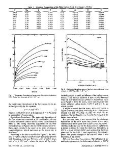
When deformed m a r t e n s t t e is subsequently t e m p e r e d , the n o r m a l sequence of p r e c i p i t a t i o n of c a r b i d e s Is also significantly a l t e r e d , t-s This communication d e scr~bea the r e s u l t s of e x p e r f m e n t s t a t t l e d out to study the effect of p l a s t i c deformation and e l a s t i c s t r e s s e s on the (211) X - r a y diffraction line width of a medium carbon m a r t e n s i t e . Small rods of AISI 1045 s t e e l were heat t r e a t e d and die drawn in a manner s i m i l a r to those d e s c r i b e d by M i l l e r and B r e y e r . 4 The p r e d e f o r m a t i o n d i a m e t e r s for the rods were so s e l e c t e d that deformation by drawing through a 0,175 in. diam die r e s u l t e d in r e ductions ranging f r o m 0 to 6 pct. Specimens, about 1~ in. in length, were cut from these b a r s . The s p e c i m e n s were c h e m i c a l l y polished in a 2:1 mixture of phosphoric acid and 20 pct hydrogen peroxide. Approximately 0.0525 in, was r e m o v e d from the s u r f a c e . A XRD-5 General E l e c t r i c D l f f r a c t o m e t e r with f i l t e r e d CrK~ r a d i a t i o n and a p r o p o r t i o n a l counter tube was used to r e c o r d (211) diffraction lines. A 3 deg beam slit, masked to produce a r e c t a n g u l a r beam of size about 0.375 in. • 0.030 in., and a 0.2 deg detector s l i t were used in these e x p e r i m e n t s . The beam impinged in a narrow line on the specimen surface p a r a l l e l with the specimen axis. The s p e c i m e n s were continuously scanned at a goniometer speed of 1 deg 20 p e r min and peaks were c h a r t r e c o r d e d between the range of 145 to 160 deg. The line width at half maximum helght was d e t e r m i n e d g r a p h i c a l l y . A s t r a i g h t line background was a s s u m e d through the c h a r t r e c o r d i n g . The peak position was located using the three point p a r a b o l i c method developed by M a r b u r g e r and Koistinen. ~ The (211) line width, r e p o r t e d in Fig. 1, was d e t e r m i n e d f r o m the X - r a y scan of the c y l i n d r i c a l surface along the axis of drawing. The line sharpened with d e f o r m a tion. The c r o s s sectioned surface cut p e r p e n d i c u l a r to the axis of the specimen was s i m i l a r l y scanned with X - r a y s . However, the beam g e o m e t r y was changed to a 1 deg slit masked to produce a beam size of about 0.1 in. sq. A s i m i l a r line sharpening was o b s e r v e d although the line width at half height was l e s s (approximately 4.5 deg for the as-quenched specimen). The differences in line width again c l e a r l y r e v e a l e d the line sharpening with deformation. The d i s p a r i t y in the line widths for the surface and c r o s s section studies was a r e s u l t of the difference in beam g e o m e t r y r e -
Carbon Martensite
7-0
V. K. SHARMA AND N. N. BREYER
B r e y e r et al. have r e p o r t e d s e v e r a l ch
Data Loading...