Effects of Environment on Modlus of Low-k Porous Films Used in Back End of Line
- PDF / 406,285 Bytes
- 9 Pages / 612 x 792 pts (letter) Page_size
- 109 Downloads / 314 Views
0990-B03-15
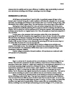
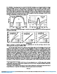
Effects of Environment on Modlus of Low-k Porous Films Used in Back End of Line Eva E. Simonyi1, Christos D. Dimitrakopoulos1, Michael Lane1, Eric Liniger1, and Willi Volksen2 1 IBM T. J. Watson Research Center, 1101 Kitchawan Rd., Yorktown Heights, NY, 10598 2 IBM Almaden Research Center, 650 Harry Rd., San Jose, CA, 95120
Abstract Reliability is an important requirement for newly developed porous low-k interlayer dielectric (ILD) materials that are being introduced into the back-end-of -line (BEOL). Dependence of Youngís moduli, as measured by nanoindentation technique, on the environmental factors, such as high relative humidity, water immersion and thermal recovery is presented along with FT-IR spectra for films with different k values. The effect of the moduli changes on cracking behavior is also discussed.
Introduction Decreasing integrated circuit feature sizes in the BEOL pose increasing reliability challenges for low-k ILD materials, with low fracture toughness. Some process steps during manufacturing, such as chemical mechanical polishing, expose the films to humidity and /or water. It is important to investigate the effect of such exposures on the mechanical characteristics of pristine films and to ascertain if adversely affected films can be restored after H2O exposure. Two types of materials are investigated: PECVD deposited p-SiCOH (Sample A) and a spin-coated organosilicate ILD of different chemical composition (Sample B). Both are low-k, porous dielectrics. Modulus and hardness data are measured with a Berkovitch indenter at indentation depths of 30-40 nm in order to avoid crack creation, and cracking features are investigated with a corner cube indenter.
Experimental Hardness and modulus were measured with a Nanoindenter XP system (Nano Instruments Innovation Center) fitted with the dynamic contact modulus (DCM) head. The DCM head provides the XP system with an overall miniaturization, allowing it to perform indentations at maximum indentation forces of .01 to 12mN. The DCM machine uses a Berkovitch indenter. This is a three-sided pyramid with 65.3∞ between vertical axis and face. The instrument was operated using the continuous stiffness measurement option (CSM). This method superimposes a small oscillating force on the applied load, allowing a continuous measurement of the hardness and modulus during the indentation process. Tip calibration was based on the OliverñPharr (1) method. The indentation was done maintaining a constant strain rate. Surface was detected by a stiffness change of 4. Indentations were done up to 150 nm depth. During this process, cracking was typically
not observed. Modulus and hardness data were taken from the minimum value of the modulus and hardness vs. indentation depth curves, Fracture toughness was measured(2 ) using a CSIRO (Australia) UMIS indentation instrument equipped with a corner cube indenter diamond. The cube corner indenter is a three-sided pyramid with 35.1∞ between the face and the vertical axes. The advantage of using this sharper diamond
Data Loading...