Effects of load ratio and temperature on the near-threshold fatigue crack propagation behavior in a CrMoV steel
- PDF / 4,524,107 Bytes
- 10 Pages / 603.28 x 788 pts Page_size
- 32 Downloads / 336 Views
I.
INTRODUCTION
IN order to predict the life of a component subjected to high frequency gravity bending or flow-induced vibrations, fatigue crack growth rate (FCGR) data are needed in the near-threshold region. The FCGR behavior at the threshold level is strongly influenced by variables such as microstructure, load ratio (R = ratio of the minimum to maximum load) and environment (including temperature). 1-21 In this study, the influence of load ratio (in the range of 0.1 to 0.8) and temperature (in the range of 24 to 260 ~ on the near-threshold FCGR behavior of a forged CrMoV steel (ASTM A470 Class 8) is characterized. In order to allow accurate interpolation of the effects of load ratio and temperature for conditions other than for which data are available, it is necessary to develop an understanding of the mechanisms by which these variables influence the near-threshold FCGR behavior. Therefore, extensive fracture morphology characterization, measurements of residual oxide layer thicknesses on the fracture surfaces by Auger spectroscopy, and surface roughness measurements by light-section-microscopy were included as a part of this study. The concept of crack closure has been used to rationalize the influence of loading, environmental and microstructural variables on the near-threshold FCGR behavior in several alloying systems.t 25 Thus, we have performed crack closure measurements during the course of the FCGR testing. The present experimental results and observations are discussed in light of the crack closure concept.
II.
EXPERIMENTAL PROCEDURE
0.05 Cu, 0.005 A1, 0.010 Sn, 0.008 As, and balance Fe. The mechanical properties are shown in Table I. The material was austenitized at 950 ~ air cooled, and tempered at 680 ~ The steel has a bainitic microstructure with an average prior austenite grain size of approximately 35 p,m. Compact type (CT) specimens, 50.8 mm wide, 60.9 mm high, and 12.7 mm thick, were used to develop the near-threshold FCGR data. Prior to testing, all specimens were precracked in accordance with the ASTM standard E647-81. B. Fatigue Crack Growth Rate Testing
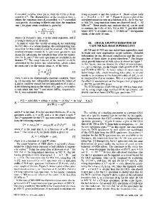
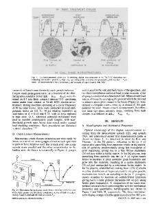
The testing temperatures were 24 ~ 149 ~ and 260 ~ and the environment was laboratory air. Heating tapes were wrapped around the specimens to obtain the desired temperature. A thermocouple mounted near the test section of the specimen surface was used to control and monitor the temperature. The relative humidity in laboratory air at 24 ~ was approximately 40 pct. The load ratios studied were 0.1, 0.3, 0.5, and 0.8. The loading frequency was 100 Hz and the waveform was sinusoidal. The crack length was determined by the compliance technique using a clip gage mounted on the front face of the specimen. The fatigue crack growth testing was conducted on a computer-controlled, servo-hydraulic fatigue machine. The PDP 11/34 computer interfaced with the machine provided the capability for automatic test control, data acquisition, and data analysis. The details of the automated system have been reported earlier. 19'26 Briefly, the stress inten
Data Loading...