Experimental observations of crystal growth in alloys rapidly quenched from the liquid state
- PDF / 544,096 Bytes
- 3 Pages / 612 x 792 pts (letter) Page_size
- 13 Downloads / 316 Views
within the thin area, and that growth would occur radially from it. The absence of any such growth center means that this suggestion is probably not correct, and indeed, it cannot account for the observed impingement boundary in the center of thin areas. We believe it is more logical to attribute such observations to crystal growth from the edges of such a thin area to the center, implying that heat extraction occurs parallel to the foil plane, and not perpendicular to it, into the substrate. The growth of grains perpendicular to the substrate does occur, however, and is readily apparent from scanning electron micrographs. Fig. 2, which illustrates such a structure, is taken from the top side of a pure nickel splat (i.e. the surface in contact with the atmosphere after solidification has ceased). The appearance of a fine-grained structure with the principle growth direction perpendicular to the foil plane indicates that heat flow has occurred in accordance with the two theoretical treatments. Unfortunately such areas are relatively thick and are seldom observable
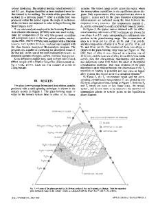
Fig. 1—Transmission electron micrograph from unthinned area of a Fe-4Mo-0.2C splat with elongated grains of S ferrite sharing common boundary A-A.
Fig. 2—Scanning electron micrograph from top surface of a nickel splat showing fine equiaxed grain structure. VOLUME 6A, NOVEMBER 1975-2153
by transmission electron microscopy unless further thinning is carried out (Fig. 3). Since splats produced by the 'gun' technique are highly porous (Fig. 4) due to their multidrop constitution, 'edge' effects cannot be ignored and indeed they have provided the areas that yielded anomalous results with respect to metastable and microcrystalline phases. 8 The other principle type of crystalline growth mor -pholgybservdinat-colmershf branched dendritic structures (Fig. 5). In unthinned foils these are invariably found in larger electrontransparent areas than are the elongated grains of Fig. 1. The measurement of secondary arms in these areas is a standard method of estimating cooling rates, 9 and the fact that secondary dendrite arms lie in the foil
Fig. 3—Equiaxed grains of austenite in a splat of AISI MI tool steel after further ion beam thinning. (Transmission electron micrograph).
Fig. 4—Low magnification scanning electron micrograph of an Ag-Sn alloy showing porosity and multidrop nature of splat (top surface). 2154-VOLUME 6A, NOVEMBER 1975
plane means that the primary dendrites from which they emanate must also lie in this plane. Since the growth direction of primary dendrites is largely determined by the prevailing direction of heat extraction, their presence in the plane of a splat foil means that the principle heat flow direction also lies in this plane. The reason why the heat flow conditions in these areas are contrary to those assumed in the theoretical analyses became clear from examination of the underside of splats by scanning electron microscopy. 6 Between 60 and 90 pct of this surface replicates the roughened copper substrate (which in this study was rou
Data Loading...