Flow Forming
- PDF / 127,099 Bytes
- 3 Pages / 504.567 x 720 pts Page_size
- 16 Downloads / 461 Views
Flow Forming Peter Groche Institute for Production Engineering and Forming Machines, Technische Universita¨t Darmstadt, Darmstadt, Germany
Synonyms Hydrodynamic spinning; Power spinning; Shear forming; Shear spinning; Shear/flow turning
Definition Flow forming is a metal forming process, classified under DIN standard 8583, used for the production of hollow components with nonuniform thickness distribution. During a flow forming process, a hollow metal blank, a tube, or a disk is fixed on a rotating mandrel and plastically deformed by one or more rollers due to the fact that the distance between the mandrel and axially moving rollers is at least in some areas of the workpiece smaller than the initial thickness of the workpiece.
Theory and Application Flow forming comprises processes during which rollers are moved along the axial direction of a
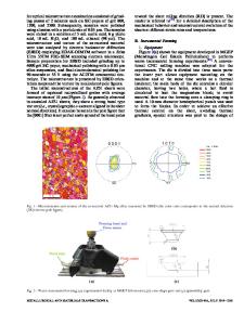
rotating preform. The movement of the rollers leads to a reduced thickness and increased length of the part. Longitudinal sections of the created products can be cylindrical, cone-shaped as well as convex or concave curved. Processes leading to cone-shaped or convex or concave curved longitudinal sections are covered by shear forming. Cylindrical shapes of longitudinal sections can be achieved by cylindrical flow forming. This variant of flow forming is described in the following. Typical products made by cylindrical flow forming possess good surface quality and high geometrical accuracy. They can be found, e.g., in hydraulic or pneumatic cylinders, wheels, and gearing mechanisms. The principle of cylindrical flow forming is shown in Fig. 1. The blank or tube is fitted into the rotating mandrel. The rollers move along the workpiece axis and deform it plastically in the vicinity of the contact zone. In doing so, the initial wall thickness S0 is reduced to S1 and material flows in the axial direction. At the same time, the initial length of the workpiece L0 is increased. The final workpiece length can be calculated under the assumption of volume constancy. By adapting the parameters feed rate v as well as the attack angle g and the trailing angle d, a desirable material flow can be achieved. Small attack angles lead to a large circumferential material flow. In consequence, bulge formation in front of the rollers can be observed. Too large attack angles on the other side induce surface waviness (Wong et al. 2003).
# CIRP 2015 The International Academy for Production Engineering et al. (eds.), CIRP Encyclopedia of Production Engineering, DOI 10.1007/978-3-642-35950-7_16750-1
2
Flow Forming
Flow Forming, Fig. 1 Principle of cylindrical flow forming (Runge 1993)
Flow Forming, Fig. 2 Principle of forward 1 and backward 2 flow forming (Runge 1993)
Improvements of cylindrical flow forming are achieved by usage of several rollers which are shifted in axial and circumferential direction. Since this measure is very effective, it is often applied. It also allows for different shapes of the rollers. This can help to overcome the limitations of material flow caused by the selectio
Data Loading...