Formation of Dislocations in NiAl Single Crystals Studied by in situ Electrical Resistivity Measurement
- PDF / 439,061 Bytes
- 6 Pages / 414.72 x 648 pts Page_size
- 53 Downloads / 357 Views
2000 MPa at 77 K. The high yield strength makes [001] NiAl a suitable material for investigating the effect of high stress on dislocation nucleation. The NiAl single crystal was annealed at 1200 C for 7 days in vacua, and was slowly cooled to the room temperature inside the vacuum furnace. The crystal orientation was determined with Laue X-ray back-diffraction. Thin tensile specimens were prepared with mechanical grinding and electro polishing. Figure 1 shows a photograph of a prepared I-shaped tensile specimen. The two broad ends were for load transmission and for attaching the four-probe terminals for the resistance measurement. The gauge length, between the shoulders, is 24 mm. The cross-section over the gauge length is 0.24mm by 0.4 mm. The axial orientation of the specimen is [001]. [001]
S4
Figure 1. A photograph of a prepared tensile specimen.
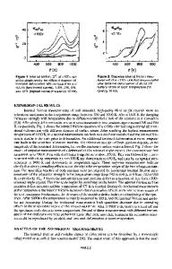
Testing Methods Testing involves loading the wire specimen in tension at a constant strain-rate and measuring simultaneously the changes in the resistance. For electrical insulation from the mechanical testing system, the transmission of load to the specimen was via two circularly cylindrical alumina adapters each with two perpendicular slits, one across the diameter for supporting the specimens and the other for specimen loading and retrieval. A schematic drawing of the adapter is shown in Figure 2. The adapters are fitted onto the metal fixtures of the tensile testing machine. For electrical resistance measurement, pure Ni wires were used as leads and were spot-welded onto the broad faces of the tensile Fig.2. The method specimens. Spot welding was used because of the expected need to used for loading test the specimens at high temperatures. With careful cleaning, NiAl specimens. and Ni exhibited excellent weldability. The weld points lay outside the slits in the load adapters and were not strained during the test. The weld spots caused some contact resistance which affected the reading of the absolute resistance of the specimen, but did not affect the measurement of the change of the resistance with load and displacement. For the resistance measurement, a four-terminal AC (alternating current) micro-Ohmmeter with ýtQ resolution was used. The micro-Ohmmeter has a built-in standard that is maintained at 35 'C thus the measurement is independent of the ambient temperature. The AC current is used to eliminate thermal EMF or thermo-couple effect due to the inevitable temperature gradient in the leads. The resistance data was collected at 30 second intervals during the test. All the tests were conducted in air. The strain rate was 10-6 per second. A 25 pound load cell was used to measure the loading force. RESULTS The Brittle Regime In the temperature region up to 242 'C, [001] NiAl is fully brittle with no visible plastic deformation. Figure 3a below shows the result of a test at 229.9 'C. The solid curve is the stressstrain curve and shows brittle fracture at 1320 MPa. The resistance, shown by the symboled 50
curve, increases approximately linearly with strain, up t
Data Loading...