High-Endurance Scalable PZT Capacitors Using Thin SRO/Pt Stacked Electrodes
- PDF / 3,074,978 Bytes
- 6 Pages / 417.6 x 639 pts Page_size
- 57 Downloads / 288 Views
Mat. Res. Soc. Symp. Proc. Vol. 596 ©2000 Materials Research Society
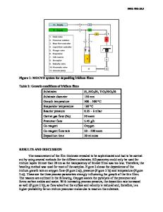
realize the best crystallization conditions on various kinds of substrate (Pt coated Si was used to compare ferroelectric properties as described later). RTA process was carried out to suppress second phase formation. Another SRO film was formed as a top electrode followed by Pt deposition. The SRO film was crystallized at 650TC before, or after, Pt top electrode deposition by RTA. Most of the films were annealed at 650'C in oxygen for an hour to improve the top electrode/PZT interface. SEM, TEM, XRD, SIMS and XPS analyses were used to evaluate the structural properties of PZT capacitors. The top electrode patterns were prepared by sputtering through shadow masks or reactive ion etching with Ar/Cl 2 plasma for electrical measurement. RT6000 ferroelectric tester was mainly used with various pulse trains. PZT capacitors with only Pt/thin SRO top electrode structure were investigated to study the effects of SRO on PZT performance. RESULTS AND DISCUSSION Introduction of SRO on PZT capacitors First, in order to investigate the effects of SRO on PZT ferroelectric properties, top Pt/thin SRO electrodes were prepared on PZT films crystallized on Pt. Figure 1 shows a TEM image of a Pt/thin SRO top electrode PZT capacitor with EDX data. A columnar-structure PZT film with crystallized SRO electrode was observed. Although it has been reported that Sr or Ru diffused from SRO into PZT results in formation of some conductive oxides such as Pb2Ru 2OT7 - and PbSrO3 and large leakage current,13] no prominent degradation was shown due to thinner SRO films stacked with Pt. No diffused elements were detected at the grain boundaries by EDX. It is considered that less Sr and Ru diffusion and good crystallinity by thickness reduction suppress the leakage. The role of SRO in fatigue test was studied based on a comparison of Pt/PZT/Pt and Pt/SRO/PZT/Pt capacitors as shown in Fig. 2. It is recognized that top Pt/SRO electrodes dramatically improve the fatigue property. Less fatigue resistance is observed for hightemperature-crystallized PZT films in Pt/SRO/PZT/Pt capacitors.
.j ........... ..... ii~ii:i
Figure 1. Microstrcture of top electrode Pt/SRO and PZT interface. No interdiffusion is observed.
248
1.0 o
Z
S~~Pt/PZT/Pt 0.5
0 o.
[Vb ]
._
[VPbI
Fatigue 5V measurement 5V Bipolar
"00.0 ._a E 0 0Z
Domain
PZT 150nm HT: 750 °CRTA LT: 550 =CRTA
pinning
Pt/SRO/PZT/Pt LT
-1.0 1
2
-4
3 4 5 Fatigue cycle (logN)
Mobile Vo" 0..,,
Figure 2. Fatigue properties of Pt/PZT/Pt and Pt/SRO/PZT/Pt capacitors.
Figure 3. Defect distribution model.
Fatigue mechanism and effects of SRO In order to clarify the fatigue mechanism, various pulse trains were used to stress PZT capacitors. From the results for fatigue behavior of a Pt/PZT/Pt capacitor using different fatigue pulse width, it is noticed that polarization reversal, not DC voltage stress mainly degrades the polarization. The fact that no degradation is observed in the case of unipolar pulse trains supports the d
Data Loading...