Inclined Substrate Deposition by Evaporation of Magnesium Oxide for Coated Conductors
- PDF / 3,020,147 Bytes
- 10 Pages / 417.6 x 639 pts Page_size
- 69 Downloads / 255 Views
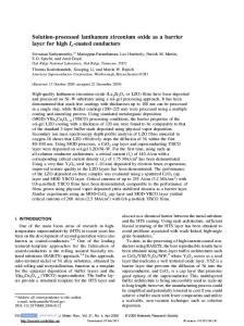
substrte quartz crystal monitar
/ Sevaporation source Figure 1. Experimental setup for inclined substrate deposition. The evaporation source was an egun with MgO or Mg target. an oxidation zone with increased oxygen pressure. A MgO single crystal substrate is deposited together with the ISD substrates as a monitor of the YBCO deposition process. The YBCO films on these monitor substrates had critical temperatures between 86 K and 90 K indicating high quality YBCO films. The critical current density jc was determined inductively and resistively at 77 K in liquid nitrogen. The inductive measurement with a 3rd harmonic method was used as a standard characterization tool as it is a nondestructive method. In order to measure the anisotropy of the critical current density, the films were patterned with a cross like bridge for resistive measurements. The width of the bridges was 0.6 mm and the length 3.6 mm. A criterion of 1 iiV/mm was used. RESULTS AND DISCUSSION ISD buffer layer To investigate the structure and texture of the MgO films, the deposition parameters like substrate inclination, deposition rate and film thickness were varied. The exemplary results, which are shown below, are from MgO deposition experiments if not mentioned otherwise. Similar results were obtained in the case of reactive evaporation of Mg. The results of these investigations are important to understand the properties of the YBCO films and will be used for the motivation of a growth model for ISD that can explain the texturing. Figure 2 shows the scanning electron microscope (SEM) image of the fracture cross section of an ISD buffer layer. It reveals a pronounced columnar structure. In this image the columns are tilted slightly away from the vapor direction which is indicated by an arrow. In general the columns are always oriented about parallel to the surface normal. SEM images also reveal that the general shape of the columns is not round but faceted. This means that the tip is a plane which is tilted towards the deposition direction, as it can be seen in figure 2, and also the
36
vapor beamn------Z direction
--
-
Figure 2. Fracture cross section of an ISD film deposited by reactive evaporation of Mg (SEM image). M&O (002) pole ft=r
(002)
Figure 3. (002)-pole figure of an ISD MgO film. a is the angle between the substrate normal and the deposition direction indicated by the x. P is the angle between the substrate normal and the (002)-pole. and also the sides of the columns are planes. The pole figure of an ISD buffer layer is shown in figure 3. In contrast to the common case the [001 ]-axis is not parallel to the substrate normal but tilted by the texture angle P3towards
37
the deposition direction which is indicated in the pole figure, too. Due to the tilt, the poles of the (100) and (010) planes are clearly visible and indicate a high degree of texture. The in-plane alignment of the film, measured by wp-scans of the (220) peak, was 8' FWHM. If we compare the pole figure and the SEM image, we find that the facets of the growth co
Data Loading...