Indentation Creep Analysis of Amorphous Nitrogen-Containing Carbon Films
- PDF / 312,445 Bytes
- 5 Pages / 414.72 x 648 pts Page_size
- 27 Downloads / 381 Views
Mat. Res. Soc. Symp. Proc. Vol. 505 @1998 Materials Research Society
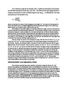
ion accelerating voltage[ 1 ], The film thickness was kept 2.7 p m by selecting optimum deposition duration. The common thickness of these films was determined one-dimensional surface roughness tester (Tokyo Seimitu Co, surfcom 550A) and a cross-sectional scanning electron microscope (JEOL JSEM-300). The relative nitrogen fraction [N]/([N]+[C]) of the resulting films is determined by the results of X-ray photoelectron spectroscopy (XPS, using a VG Scientific Co. ESCALAB 210). A Forier-transform infrared (FTIR) spectrometer (JASSCO IR-810) was used to detect the absorption bands due to C-H, C-N and N-H bonding. The micro-hardness and indentation creep characteristics of the samples evaluated using a nano-indentation micro-hardness apparatus (Helmut Fischer Gmbh+Co. Fischerscope H l00V) at a constant temperature of 24°C. The function of this system is to determine, having a resolution of 2 nm, the depth of penetration of an indenter tip as a function of the applied force with a resolution of 0.02 inN. A diamond Vickers indenter tip was used with a geometrical correction procedure to accurately calculate hardness. For time-dependent indentation depth measurement, the indenter was first brought into contact with the film at minimum applied force, and then the applied force was increased to 500 mN during a period of 4 s. The creep test was started after this procedure. 3. Results and Discussion The indentation procedure is carried out through measurement of the total displacement d t for each second, under an increase in the applied force F to 500 raN, during a period of 30 s. The hardness of the DLC film and nitrogen-containing carbon films is basically defined as the quotient of the applied force F to 500 mnN divided by the surface area of the resulting indentation. The indentation surface area is derived from the measurement of the total indentation depth d t and the well-defined geometry of a diamond Vickers indenter. Figure 1 shows the hardness value versus nitrogen fraction [N]/([N]+[C]) of nitrogen-containing carbon films. The nitrogen fraction of the films calculated using photoelectron intensity at Cls and NIs signals obtained from the XPS. The hardness values 4.8-6.2 GPa are found to be comparable to DLC without nitrogen doping. In addition the hardness values does not show significant changing with nitrogen fraction.
10
25
film [NJ[Nj+O)=O.OO
SDI
cc
508-: [
-C
5
15
cfD4o.056
0: [N~jN][NCDaO.061
CC
A : [NAM[N4CD4O.064 X: [II/1NIC]CD=O.OO
0.055
0.06
4 12g45678910
0.065
Time (s)
[NY([N]+[C]]) ratio
Fig.2. Typical results of the time-dependent
FIg.l. Hardness of the nitrogen-containing
Indentation depth of the DLC and
carbon films deposited at various Va. Dashed line represents hardness of
nltrogen-containlng carbon films deposited at various relative nitrogen fractions.
DLC film deposited at Va=200V.
206
In contrast, there is a significant difference on the creep behavior between amorphous hydrogenated carbon films
Data Loading...