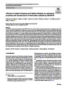
Influence of heat treatments on microstructure, mechanical properties, and corrosion resistance of weld alloy 625
- PDF / 5,823,484 Bytes
- 14 Pages / 613 x 788.28 pts Page_size
- 26 Downloads / 473 Views
I.
INTRODUCTION
A L L O Y 625 features good mechanical strength, combined with good corrosion resistance and good weldability characteristics. It can be used for welding lowalloyed steels or high yield strength steels with alloy 625 for repairing these steels by welding ~.2.31 or by coating process in order to protect them from corrosion. 14,51 In such cases, post-welding heat treatments are necessary to preserve the characteristics of the heat affected zone (HAZ) of ferritic steels. As few data were available on the evolution of the structure and properties of alloy 625 during industrial heat treatments, 16'7"8~ a first study was conducted on a forged bar. 191 It has allowed for determining the temperature ranges within which the different phase precipitations occur and establishing a link between the mechanical properties and corrosion resistance versus the microstructure of the parent metal 625. This article presents the results obtained on the effects of industrial-type heat treatments (eight-hour hold times at temperatures between 600 ~ and 1000 ~ and air cooling) on the microstructure, mechanical characteristics, and corrosion resistance of weld alloy 625 in sea water and chloride environments. F. CORTIAL and J.M. CORRIEU, Engineers, Metallurgy Service, and C. VERNOT-LOIER, Head of Metallurgy Service, are with the Centre d'Etude des Structures et Mat6riaux Navals, DGA/DCN INDRET, 44620 La Montagne, France. Manuscript submitted January 31, 1994_
METALLURGICAL AND MATERIALS TRANSACTIONS A
II.
EXPERIMENTAL PROCEDURE
A. Material
Weld metal 625 used for the study originated from a weldment of 32 x 150 x 750 m m 3, obtained by automatic tungsten inert gas (TIG) welding process on an A533 steel plate of 90 x 230 • 940 m m 3. The essential welding parameters are given in Table I. The chemical compositions of the wire and deposited metal are given in Table II. After flush grinding the 30-Am weldment, eight pieces 170 x 65 x 30 m m 3 in size were cut with their length parallel to the direction of the deposited metal, as shown on Figure l(a), the A533 steel area being eliminated by milling of the eight pieces. Each piece was sized to incorporate the dilution area with the A533 parent metal and the amount of material necessary to conduct all the tests. Systematically, machining was performed so that the useful areas of the test specimens were situated outside the dilution area. The seven pieces, identified F to I and K, M, and N, on the analogy of the identification used for the preceding study on forged metal, t91 were heat treated (Table III) under the following conditions: heating in 50 ~ increments per hour, eight-hour hold time at the selected temperature, cooling in air at a cooling rate of 900 ~ B. Tests
The test specimen sampling plan is identical for the different thermal states (Figure 1(b)).
VOLUME 26A, MAY 1995--1273
Table I.
Welding Parameters
Wire Diameter (mm)
Gas
Current (A)
Voltage (V)
Speed (cm. min- t)
Wire Feed Rate (m. m in- i)
0.8
pure Ar
170 • 5
13 • 0.2
10 --- 0.2
2 • 0.05
Data Loading...