Injection Efficiency from Various Metals into Trap Free Molecularly Doped Polymers Evaluated from Combined Analysis of C
- PDF / 488,132 Bytes
- 6 Pages / 414.72 x 648 pts Page_size
- 90 Downloads / 240 Views
(1)
Here Eis the relative dielectric constant, [Lis the drift mobility, E is the field defined as V/L where L is the film thickness. At a given field for fixed specimen geometry the current supplied by an ohmic contact is uniquely specified by the drift mobility of the injected carrier at that field. If we 629 Mat. Res. Soc. Symp. Proc. Vol. 488 ©1998 Materials Research Society
measure the drift mobility at a given field and calculate JscLc then compare this calculated current density to the current injected in the dark JDc by a contact under test on the same specimen we can define an injection efficiency figure of merit F, under fully self-consistent conditions namely:
(2)
F = JDC/JTFSCLC EXPERIMENTAL
Figure 1 is a schematic of the experimental apparatus4 Unipolar hole transport specimen films were configured as thin film parallel plate capacitors with the contact under test on one face, and the opposite contact blocking and transparent (typically a 300 A semi-transparent evaporated Al film) as required for the execution of small signal current mode TOF experiments
/
ý,Lser
10-2 fill
I I
10-
N
Blocking contact
-4CC10
TPD/polycarbonate
om 0' 05
Digitizer
•
supply
- C-D2
•
E
Contact test I Fast switch • underR•@[1~plr
"Bipolar +
' "
on
"
10"0 10-7
o
,,1 S10"8;
323K
"d= 9.4! microns 1,,, 101
104
E (V/cm) Figure 1. Experimental apparatus for analyzing injection efficiency of a test contact.
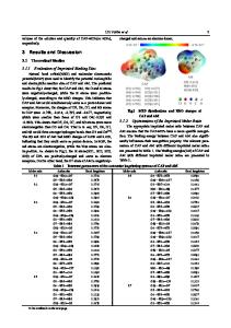
Figure 2. Measured J vs. E (filled squares) compared with J computed from drift mobility data using equation 1.
The TOF technique was used to make measurements of hole drift mobility. With positive bias applied to the Al semi-transparent blocking contact the specimen film was photoexcited with a highly attenuated 337 nm pulse from a nitrogen gas laser. Transit times ttr for photoinjected holes at the applied bias could then be determined from the current transient and the mobility calculated from m = L2/(tV). In the present case, e.g. evaluation of hole injecting contacts, steady state J-E measurements were done by application of a positive step voltage to the contact under test, capturing the transient for additional analysis, and then waiting for the current to achieve a steady state value. RESULTS Figure 2 is a plot of current density J versus electric field E for a thin film of a MDP composed of a 40 wt% solid solution of TPD in a polycarbonate binder. The molecular structure of the tertiary arylamine TPD is shown in the figure. The polymer film was solvent coated onto a carbon loaded polymer film substrate (Myst-R®) and then overcoated with an evaporated semi-transparent Al top 630
contact. The hole drift mobilities, Is(E), were measured over a wide range of applied field and these values used to calculate Jansc=c(E) according to eq. 1. These data are represented by the open circles in the figure. The filled squares represent the measured steady state hole injection current density JDc supplied by the carbon filled polymer substrate contact. The measured values of the steady state dark cur
Data Loading...