Internal friction in ferrous martensites
- PDF / 1,367,272 Bytes
- 11 Pages / 612 x 792 pts (letter) Page_size
- 42 Downloads / 414 Views
w h e r e b is the B u r g e r s v e c t o r and to i s the effective d i m e n s i o n o v e r which the atom group m o v e s c o o p e r a t i v e l y . Thus, a m o n g other p o s s i b l e f a c t o r s , ~x To for the 160~ peak should be l a r g e r than To for the Sp by the r a t i o of the twin t h i c k n e s s o r width (lo i n F i g . 8(b)) to b. T y p i c a l v a l u e s of/o a r e 5 to 10 n m (Ref. 20) so that the m a g n i t u d e s of % for the 160~ peak in T a b l e II and t h e i r c o n c e n t r a t i o n d e p e n d e n c e a r e c o n s i s t e n t with Eq. [2]. To for the 160~ peak is s e v e r a l o r d e r s of m a g n i t u d e l a r g e r t h a n To of the cwp and 250~ peak. The l a t t e r ;"o's can be accounted for by d e t a i l e d a n a l y s i s of the Schoeck mechanism.3~ 3) Dependence of P e a k Height on C a r b o n Content. T h e d i s t r i b u t i o n of c a r b o n a t o m s i n twinned m a r t e n s i t e s is highly c o m p l i c a t e d . C a r b o n m a y be p r e s e n t i n solid solution, in p r e c i p i t a t e s (~, F e , C , or both d e p e n d ing on the t e m p e r i n g condition), at d i s l o c a t i o n s , and f i n a l l y at the twin b o u n d a r y s i t e s of i n t e r e s t h e r e . T y p i c a l n u m b e r s of a l l t h e s e s i t e s a r e given i n T a b l e IV. In spite of this complex p a r t i t i o n i n g the p r o p o s e d m o d e l is c o n s i s t e n t with the o b s e r v e d d e p e n d e n c e of the peak height on the c a r b o n c o m p o s i t i o n in at l e a s t two ways: i) The r e l a x a t i o n s t r e n g t h m u s t be p r o p o r t i o n a l to the c o n c e n t r a t i o n of i n t e r s t i t i a l s in twin METALLURGICALTRANSACTIONSA
(a) Et(X)
~,
~
~
~ f~CUorU
Ii -!
' !
, •
Xo X l--d-(b)
E• 1
o oro+E
c,
t L .
,
t
ii
[o Xl
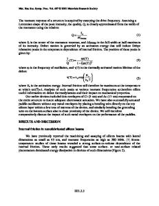
U =activation energy for mterst=tml ddfuslor~ E~cc~ =binding energy of an interstitial cluster E~ T~ =mterst~tml-twm boundary binding energy E(BTM =mterstttml-d~slocat~on binding energy
Fig. 9--Schematic representation of the potential energy wells m the vicinity of (a) a twin boundary, (b) a dislocation. The dashed curves show the change which occurs when the boundary or dislocation moves from X0 to Xt. The figure is drawn to imply that EBtcl)
>
EB(CT).
Table
IV,
A) PossibleSitesfor CarbonAtomOccupation Type
NumberAvallable/m3
Intersltlal(octahedral) {112) Twinboundary
2 55 X 1029sltes/m3 7 • 1018sltes/m2• hnearivan density (numbertwins/m) ~102~sltes/mX dislocationdensity(m/ma)
Dlslcoatlon(edge and screw average)
B) Densitiesof CarbonAtomsm Structuresand SohdSolutions Type
NumberofC Atoms/m3
e-carbide(Fe2:C) Cementlte(FeaC) 0.25 wt pct C martensite 0 4 wt pct C martenslte 1 0 wt pct C martenslte
2 8 X 1028• volumefracuone 2 6 • 1028• volumefractionFe3C 8 2 • 1026 16 X 10~7 3 3 X 1027
.
VOLUME 7A, JUNE 1976-847
unlike d i s l o c a t i o n s which, b a s e d on the behavior of the cwp, s a t u r a t e at much lower carbon c o n c e n t r a t i o n s . 4) Dependence of
Data Loading...