Kinetic Characteristics of Si 3 N 4 CVD
- PDF / 335,090 Bytes
- 6 Pages / 420.48 x 639 pts Page_size
- 9 Downloads / 429 Views
KINETIC CHARACTERISTICS OF Si3N4 CVD W. Y. LEE, J. R. STRIFE, and R. D. VELTRI United Technologies Research Center, East Hartford, CT 06108.
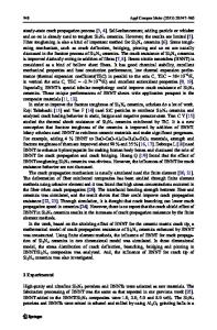
ABSTRACT The CVD of Si 3N4 from SiF 4 and NH 3 gaseous precursors was studied using a hotwall reactor in the temperature range of 1340 to 1490'C. The effects of temperature, time, flow rate, and SiF 4 /NH 3 molar ratio on deposition rate and axial and radial deposition profiles were identified. The decomposition characteristics of pure NH 3 and SiF 4 were studied utilizing mass spectroscopy and compared to thermodynamic predictions. INTRODUCTION Si 3 N4 coatings have been successfully fabricated by CVD (chemical vapor deposition) for use in various microelectronic and structural applications. Si 3 N4 can be deposited from a wide variety of silicon containing precursors such as SiCI4 , SiF 4 , SiH 2CI2 , SiH 4 , etc. NH 3 is the most widely used nitrogen-containing precursor for the Si 3N 4 deposition although N2H 6 and N2 have been occasionally used. In general, the CVD of crystalline Si 3N4 has been achieved at temperatures above -1300*C using SiCl4 -NH 3 and SiF 4 -NH 3 precursor mixtures. Kingon et al. [1] studied the thermodynamics of the SiH 4 NH 3 , SiCI4 -NH 3 , and SiF 4 -NH 3 precursor systems in the temperature range of 500 to 1700*C. Interestingly, the thermodynamic analysis predicted that Si 3N 4 would not be deposited above -1300'C from the SiF 4 -NH 3 system. Galasso and his co-workers [2-5] were able to experimentally deposit Si 3 N4 at these high temperatures indicating that deposition was controlled by kinetics and/or transport phenomena. This investigation was initiated to identify critical kinetic issues concerning the SiF4 -NH 3 CVD system. EXPERIMENTAL SiF 4 (99.99%) and NH 3 (99.9%) were separately introduced into a cylindrical graphite retort using a water-cooled, co-axial dual-path injector constructed of stainless steel. The graphite retort was placed vertically, and the gas flow direction was upward. The retort was heated by graphite heating elements which enclosed the retort. The inside diameter and length of the graphite retort were 13.3 cm and 56.9 cm, respectively. A quadrupole mass spectrometer located in the downstream of the reactor was used to monitor effluent gas composition. An orifice probe technique was used to sample the exhaust gas by differentially pumping the mass spectrometer chamber. Graphite rods of 0.63 cm diameter and 30 cm length were fixed vertically to probe deposition rate as a function of axial location in the retort. Following deposition of Si 3N 4 , the graphite rods were sectioned into 1 cm length cylinders at specific axial locations and the graphite was removed by oxidation at -650*C. The remaining coating shells were then analyzed. The utilization of a water cooled injector at the reactor inlet caused significant temperature gradients in the axial direction. The temperature profiles shown in Figure 1 were measured along the reactor centerline using a platinum-rhodium thermocouple. Peak temperatures were measured at app
Data Loading...