Material Flow Visualization during Friction Surfacing
- PDF / 317,682 Bytes
- 3 Pages / 593.972 x 792 pts Page_size
- 27 Downloads / 308 Views
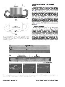
ction surfacing is an emerging technique for producing thick solid-state coatings to combat wear and corrosion. In this process, localized heating is produced by the friction generated between the rotating consumable rod and the substrate. The rubbing surface of the consumable rod undergoes intense plastic deformation at elevated temperatures, resulting in the formation of hot plasticized material, which is transferred into the substrate to form the coating. The material is transferred in successive discrete layers, which constitute the coating.[1] A typical stainless steel friction surfaced coating is shown in Figure 1. Many studies have been carried out on the feasibility of depositing a variety of materials on different substrates.[2–4] However, studies on fundamental aspects of friction surfacing are very limited, particularly on metal flow behavior during friction surfacing.[5,6] Friction surfacing involves a combination of stirring, extrusion, and forging. Hence, a simple analytical description of metal flow behavior is difficult. In this study, a marker technique is adopted to visualize the metal flow patterns in the coating during friction surfacing. The transverse cross sections of the coated regions were studied with X-ray radiography and scanning electron microscopy (SEM). The consumable material used for this study was stainless steel AISI 304, and the marker material used was tungsten powder. Two rods, 18-mm diameter and 100-mm long, were used for producing the coating.
H. KHALID RAFI, Research Scholar, G. PHANIKUMAR, Associate Professor, and K. PRASAD RAO, Professor, are with the Materials Joining Laboratory, Department of Metallurgical and Materials Engineering, Indian Institute of Technology Madras, Chennai 600 036, India. Contact e-mail: khalidrafi@gmail.com Manuscript submitted November 25, 2010. Article published online January 27, 2011 METALLURGICAL AND MATERIALS TRANSACTIONS A
Eight holes, 1.5-mm diameter, were drilled along the periphery of the rubbing surface of one consumable rod, and a 3-mm hole was drilled at the center of the second consumable rod (Figure 2). These holes were filled with tungsten powder prior to friction surfacing. X-ray radiography was conducted from the top surface of the as-deposited coatings, while the transverse cross section of the coatings was examined in the unetched condition with scanning electron microscopy in the backscattered electron (SEM-BSE) mode. Figures 3(a) and (b) show the X-ray radiograph of the coating produced with marker at the center and periphery, respectively. The distribution of tungsten powder at the starting and the middle regions of the coating is to be noted carefully. At the starting region, the location of markers corresponds to the same position as originally placed in the consumable rod. However, when the coating proceeds, there is a difference in the location of markers, which can be accounted with two stages of the coating process: (1) dwell period at the start, where the consumable rod is allowed to rotate until it attains the plastic state;
Data Loading...