Microflow in niobium alloy crystals
- PDF / 547,273 Bytes
- 6 Pages / 612 x 792 pts (letter) Page_size
- 1 Downloads / 407 Views
EXPERIMENTAL
PROCEDURE
Using high p u r i t y p o l y c r y s t a l l i n e r o d s as s t a r t i n g m a t e r i a l , s i n g l e c r y s t a l s of n i o b i u m and a l l o y s with t a n t a l u m and m o l y b d e n u m were grown by e l e c t r o n b e a m m e l t i n g . The c r y s t a l s w e r e grown u n d e r a p r e s s u r e of 5 x 10⁻⁵ t o r r by p a s s i n g a m o l t e n zone at 25 cm p e r hr along t h e i r lengths. The u n i f o r m i t y of c o m position was e s t a b l i s h e d u s i n g X - r a y f l u o r e s c e n c e a n a l y s i s ; the c o m p o s i t i o n of the alloys was 0.5, 1.7, 4.8 at. pct T a and 0.9, 4.9, and 6.6 at. pct Mo. A t y p i cal i m p u r i t y c o n t e n t was 80 wt ppm of total i n t e r s t i t i a l C, H, O, and N. The c r y s t a l s w e r e s p e c i f i c a l l y o r i e n t e d in the middle of t h e s t e r e o g r a p h t c t r i a n g l e to give F. GRAHAMWILSON, formerly Graduate Student, Metallurgy Department, University of British Columbia, Vancouver, B. C., is now Research Metallurgist, International Research and Developments Co. Ltd., Newcastle-upon-Tyne,England. E. TEGHTSOONIANis Professor and Head, Department of Metallurgy, University of British Columbia. Manuscript submitted March 26, 1970. METALLURGICALTRANSACTIONS
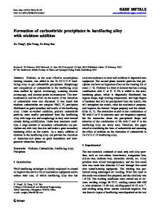
slip on the {011} system with an extensive region of easy glide. Tensile specimens were prepared from the as-grown crystals by spark lathing followed by chemical polishing. About0.25 mm was removed from the gage section using a solution of 1 part HF to 3 parts HNOa. Gage diameters were in general uniform to within 0.01 mm and typical specimen dimensions were as follows: gage diameter: 2.00 mm gage length: 20 mm shoulder diameter: 3 mm shoulder radius: 2 mm The specimens were strained in tension on a Floor Model Instron, using a crosshead speed of 0.005 in. per rain. For the macrostrain tests, strain was measured indirectly from a load-time plot on the Instron chart; for the microstrain tests, a capacitance extensometer was attached directly to the specimen gage. The construction of the extensometer and the technique for obtaining microflow curves have been described in detail elsewhere 6'I~The procedure employed is indicated schematically in Fig. I. The onset of yielding was determined by load cycling up to the stress at which a permanent set first occurred. This is called the anelastic limit or microyield stress, r a. (The elastic limit, Te, at which a hysteresis loop first forms, was not investigated.) The anelastic limit also defined the "anelastic slope" of the microflow curve which was subsequently obtained by continuous straining up to the macroflow stress, rf, defined as the stress at which gross plastic flow occurs. The macro-
Anelaslic
line
~~ T ~ ~r
0
Elongation Fig. 1--Illustration of technique for obtaining micreflow curves. VOLUME 2, APRIL 1971-1183
? E E 8
E
Present work
9
Milne 8= Smal&rnan6
V
E 3O ~"
Data Loading...