Microstructure, Creep and Fracture Toughness of Directionally Solidified NiAl/(Cr,Mo) Alloys Modified with Hf, Si, Ta, T
- PDF / 2,335,595 Bytes
- 6 Pages / 412.74 x 641.7 pts Page_size
- 26 Downloads / 342 Views
ilar. All alloys were arc-melted and cast into rods 12.5 mm in diameter. Samples were sectioned in the mid-section of the cast rod, metallographically mounted and polished, and examined under optical and SEM conditions. After quantifying the results of the microstructural analyses in terms of % eutectic, % dendrite and % segregated phases, these data and alloy chemistries were subjected to statistical analyses where empirical models were built and then optimized to obtain the highest eutectic content. Select Base Alloy System, Elements for Additiotn and their
Efcenstruct DoE: Expedtst Is Eeriuantiying fodditinpadlen
Range/Levels of Investigation
Implement DOE: Cast
Complex Effectsof Several Alloying ElemensteMdl
Alloys
CollectResponse Data: Metallogmphy and
AnalyzeData: Build and Optimize Statistical
DS Processing and of Testing
Quantification of Eutectic Phases
Empirical Models
Optimized Composition opsto
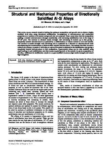
Figure 1. DOE Methodology used for Developing Directionally Solidified NiAI Eutectic Alloys
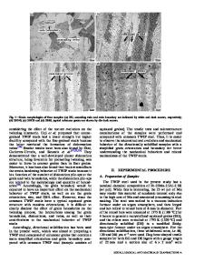
From these interactions, four alloys were chosen for directional solidification at a fixed withdrawal rate of 12.7 mm/h utilizing a modified Bridgeman technique. The directionally solidified region was typically about 19 mm in diameter and 100 mm long. The nominal and final chemical compositions after DS are presented in Table I. For creep testing, nominally 5 mm diameter by -10 mm long cylindrical compression specimens were wire electro-discharge machined (EDM) from the as-grown bars with sample length parallel to the growth axis. Compressive stress - strain behavior at engineering strain rates ranging from about 2 x 1074 s1 to 2 x 10⁻⁷ s1 were measured in air at 1300K under constant crosshead velocity conditions in a universal test machine. A few samples were also tested in air at 1300K under constant load compressive creep conditions in lever arm test machines. Fracture toughness of the alloys was measured using a chevron-notch flexure specimen in accordance with ASTM test method PS070 for ceramics [8]. Four test specimens per alloy, measuring about 3 mm in thickness and 6 mm in width, were loaded at a stroke rate of 0.05 mm/min between 20 and 40 mm spans (i.e. configuration "C" of PS070). The specimen stability was monitored by either placing a strain gage on the specimen compressive [9] face or with an extensometer contacting the load train. Both methods were adequate for assessing the crack stability. RESULTS AND DISCUSSION Typical back-scattered electron (BSE) micrographs of the arc-melted alloys from DOE are presented in Figure 2. The alloys were comprised of up to 4 different microstructural features: a 2-phase eutectic region with lamellae of the NiAl phase and (CrMo) phase; a 3-phase eutectic consisting of the previous two phases and (based on energy dispersive spectroscopyEDS, and X-ray diffraction) a Laves phase (i.e. Cr2Ta); NiAl dendrites; and intercellular phases. The statistical empirical models built were used to optimize the total amount of eutectic phases (2 + 3 phase eutectic). From these
Data Loading...