Nomenclature for metallographic sections
- PDF / 97,276 Bytes
- 1 Pages / 594 x 774 pts Page_size
- 92 Downloads / 355 Views
(a) ST
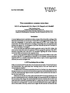
J.R. PICKENS Elaborate and unambiguous nomenclature has been devised by Goode t for fracture toughness test specimens depicting both the axis of loading and the direction of crack propagation. This nomenclature is used by the American Society for Testing Materials (ASTM) 2 and enables investigators to discriminate readily among the various fracture toughness specimen orientations without resorting to verbose descriptions in written communications. For example, using this notation for extruded bar, two fracture toughness specimens having different loading axes such as the short transverse (S) and long transverse (T), but the same direction of crack p r o p a g a t i o n - - e . g . , the longitudinal (L) direction--can be easily described as S-L and T-L specimens, respectively. This notation is widely accepted and extremely useful. Surprisingly, there is no simple notation for describing planar metallographic sections that receives widespread usage. Investigators often refer to longitudinal or transverse sections of rectangular bar or plate, a terminology that can be ambiguous. Clearly, a longitudinal section may be made in two different ways, such as parallel or perpendicular to the "top" surface of plate, with each section potentially exposing a different grain morphology, texture, and secondphase particle distribution. In some communications, ambiguities exist as to whether a particular micrograph is from a "longitudinal section" or whether the viewer is looking along the longitudinal direction of the wrought product. The following simple notation is used in our laboratory to avoid such ambiguities. Each of the three commonly investigated, perpendicular planar sections is described by two of the three symbols for directions defined in Figure 1(a). The two symbols describe the orthogonal directions that are contained in the plane being described. For example, a metallographic examination of the "top surface" of rolled plate would be of an L-LT section because the longitudinal and long-transverse axes lie in that planar section. The proposed notation clearly discriminates between this section and one used to examine the "side" of the rolled plate, which would be an L-ST section (Figure l(b)). By convention, the symbol of the direction in which the longer dimension of the wrought product exists is placed first in the notation. For example, the aforementioned "top surface" is described by L-LT, and not LT-L, because the wrought product is longer in the L than the LT direction, This simple notation eliminates ambiguity and reduces the verbiage needed to describe a metallographic section.
J.R. PICKENS is a Senior Scientist and Group Leader of Advanced Alloys Research at Martin Marietta Laboratories, 1450 South Rolling Road, Baltimore, MD 21227. Manuscript submitted December 11, 1985.
METALLURGICAL TRANSACTIONS A
L
= Longitudinal
LT = L o n g t r a n s v e r s e ST = S h o r t t r a n s v e r s e
Fig. 1--Definitions of (a) axes and (b) planar section notation for extruded bar or rolled plate.
REFERENCES I
Data Loading...