On the geometrical representation of phase equilibria
- PDF / 948,024 Bytes
- 10 Pages / 612 x 792 pts (letter) Page_size
- 91 Downloads / 464 Views
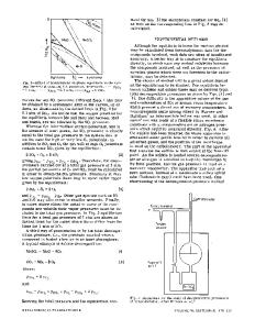
A phase diagram r e p r e s e n t s the geometrical loci of thermodynamic p a r a m e t e r s when equilibrium between different phases under a given set of conditions is e s tablished. The term "phase d i a g r a m " in metallurgy and chemistry applies to many different sorts of twoand three-dimensional representations of phase equilibria. Among the most familiar are t e m p e r a t u r e p r e s s u r e (T-P) diagrams for one-component systems such as in Fig. 2(b) for a substance such as water (type 1) and also temperature-composition i T - n l / ( n 1 + n2)] diagrams in binary systems such as in Fig. l(a) for the Fe-O system (type 2). A third familiar diagram is the isothermal composition representation for a t e r n a r y system (type 3), which is usually plotted on the "Gibbs t r i a n g l e " as, for example, in Fig. 10(d) for the Ni-Mg-O system at 1300~ The topological rules governing the construction and interpretation of such diagrams are well known. 1 There are many other types of phase diagrams, however, which conform to the same topological rules. For example, the p r e s s u r e vs composition plot of a hypothetical binary system at constant t e m perature in Fig. 3(a), and the plot of temperature vs log PO~ in the Fe-O system in Fig. l(b) are topologically similar to temperature vs composition and temperature vs p r e s s u r e diagrams, respectively. In the present paper, conditions sufficient for a phase diagram to obey the topological rules of one of the three prototypes mentioned above are examined. Following this, three types of phase diagrams for t e r n a r y systems which prove quite useful are discussed in detail. The usefulness of these diagrams
is greatly enhanced by the fact that, although uncommon, their construction and interpretation are immediately apparent to anyone familiar with temperature vs composition or temperature vs p r e s s u r e diagrams. 1) GENERAL CONSIDERATIONS Generalized thermodynamic potential functions may be defined as follows:
T = (~U/~S)v,n j
[1]
- P = (OU/ 8V)S,n j
[2]
P'i =
[3]
( O U / ~ n i ) s , v , nj(j~i)
The thermal potential T, the mechanical potential - P , and the chemical potential ~i each correspond to a certain form of energy (thermal, mechanical, chemical), and each is defined as the rate of change of internal energy U with the conjugate extensive variable. (The reason the mechanical potential and its conjugate
hi riFe
5-Fe +l i q u , ~
,60-~ 0' ~
hernah~e + oxygl
licit d oxide
Iqui~ Fe I
f400
,~• ~g__/____ ~. tOO0
~-Fe ] w~stite ~oo "+wd ;tite [ + m ~ n e t i t e
ceFe
~
h~ nah~
/
A. D. PELTON, formerly with the Institut for theoretische H~ttenkunde und angewandte physikalische Chemic der Technischen Universit~it Clausthal, West Germany, is now with the Department of Metallurgy and Materials Science, Massachusetts Institute of Technology, Cambridge, Mass. 02139. H. SCHMALZRIED is with the Institut fiir theoretische Htittenkunde und angewandte physikalische Chemic der Technischen Universit~t Clausthal. Manuscript submitted Septe
Data Loading...