Properties of Piezoelectric PZT Thin Films for Microactuator Applications
- PDF / 401,285 Bytes
- 6 Pages / 414.72 x 648 pts Page_size
- 23 Downloads / 432 Views
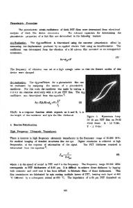
membranes was 4 mm, the thickness of the silicon was 10 to 30 gim, and the PZT film was 0.6 gim thick. The membranes were used to fabricate micromotors and full description of their preparation, and the configuration and performance of the micromotor can be found in Ref. [4], where results with sputtered PZT films are also presented. CHARACTERIZATION OF THE PIEZOELECTRIC PROPERTIES OF FILMS USING OPTICAL INTERFEROMETRY Determination of the piezoelectric coefficients of piezoelectric thin films is not a simple task because of the small thickness of the films and their strong clamping to the substrate. The expected displacements due to true piezoelectric effect, even for the electric fields comparable with coercive field, do not exceed 1 A. Therefore, optical interferometry is often utilized to determine the longitudinal piezoelectric coefficient, d 33 , by means of the inverse piezoelectric effect. Up to now, only few results concerning piezoelectric measurements of ferroelectric films have been reported [7-10]. In this investigation, a simple Michelson interferometer [11] was used to measure displacement of FTSS and membranes under external AC electric field. Details of the experimental setup and of the measurement method will be given elsewhere. The main disadvantage of this experimental scheme is that the displacements of only one face of the sample can be monitored and therefore movement of the whole sample as a rigid body can not be excluded [11]. This problem may be overcome for the bulk samples by clamping the back side of the sample to a rigid holder, and by using samples in a cubic form to prevent the bending effects [12]. In the case of FTSS, the substrate and the film effectively form a bimorph structure resulting in large bending effects even if the frequency is much smaller than the resonance frequency of the flexural mode. Such a behaviour was observed earlier for transverse electroded PLZT films [13]. Under such circumstances, the measured response will not reflect the longitudinal piezoelectric coefficient d 33 , but rather the transverse coefficient d 31 which is effectively increased by the multiplication factor of the bimorph. This is illustrated in Fig. la and lb where the displacement of the PZT film on free (unclamped)
40
35_
..... 358......... ....... 8
25
U20
[email protected]@e@0._
40
7
E~15
1) 10 ._ 5
unclamped osubstrate b)
60
30
20 a)O
ME
-200 _•
•
: .
EL-40.:
1 i
-M MM S
E
t clamped substrate
'i-60"
0)
1
0.2 00iameter 0.8 11 1.2 o 1.4 m1.6 1.21.Distance 0. 0.4 0.4 0.6 0.6 0.8
Diameter of the top electrode (mm)
0 0.5 1 -0.5 1 05 0 -. the center of the electrode (mm) from
Fig 1. a) Displacement of the PZT film on unclamped substrate as a function of top electrode diameter. b) Displacement of the PZT film on unclamped and clamped substrate as a function of distance from the center of the top electrode. The arrows indicate electrode width. The
frequency of the AC field was 1 kHz, with amplitude 0.1 V for the free and 0.2 V for the clamped substrate.
substrate is pl
Data Loading...