Scintillation Mechanism and Radiation Damage in Ce x La 1-x F 3 Crystals
- PDF / 643,497 Bytes
- 7 Pages / 414.72 x 648 pts Page_size
- 75 Downloads / 314 Views
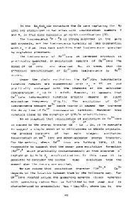
of the experimental facilities employed for VUV experiments at Orsay, and for radiation damage experiments at Brookhaven, are given in Ref. 5. The emission spectra under VUV excitation are shown in Fig. 1. These are similar to those reported previously [4-8]. Note, however, that the emission under 125 nm excitation (a band-to-band transition) obviously contains a significant contribution from Ce. The near UV band, attributed by Moses, et al. [8], to a self-trapped exciton (STE) is much broader and peaks at =350-400 nm. Fig. 2 shows light output as a function of excitation wavelength. The excitation spectrum of the 0.01% Ce sample (trace a) clearly shows large individual peaks, associated with 4f-5d transitions and additional low intensity structure with two shorter wavelength peaks. The first of these, at 160 nm, had previously been interpreted as a 4f-6s transition [8,9] with possible contribution from a charge transfer transition [9]. The second, at 125 nm, has been interpreted as a band-to-band transition [8,10]. In absorption spectra the intensity relationship is reversed, with the Ionger wavelength 4f5d transitions characterized by moderate oscillator strengths of the order of 10-21[4,5], and a much stronger shorter wavelength absorption that begins at 160 nm and peaks at about 147 nm [9]. Both photoionization and charge transfer transitions are usually characterized by much higher oscillator strengths. In regions of high optical absorption, excitation spectra can be severely distorted, which may make the peaks appear to shift significantly. Such large differences between observed absorption and excitation spectra, as those reported here, are often indicative of high-rate nonradiative transitions. Although there are clearly significant distortions in the 4f-5d range of the 10% Ce sample spectrum as well (Fig. 2, trace b), it is likely that the relative contribution of shorter wavelength excitation is even smaller than in the 0.01% Ce sample. However, the very presence of4this structure2 indicates that a small contribution to the Ce emission does come from electron-Ce ÷ or hole-Ce ÷recombination. This will be discussed later. Fig. 3 presents the luminescence pulse shapes under pulsed synchrotron excitation. Trace a is the pulse shape of the 300 nm emission from the 0.01% Ce sample under 220 nm excitation at 10 K; the decay time is measured as 18.3 ns, with background below 0.4% of the total signal at
a) a)).
a)
•
b)
b)
0 Cb
C)
C
b) 250
300
350
400
450 100
150
200
250
300
0
50
Wavelength (nm)
Wavelength (nm)
Time (ns)
Fig. 1
Fig. 2
Fig. 3
100
Fig. 1. Luminescence spectra of LaF 3 :0.01 %Ce at 10 K. Trace a, excitation 220 nm; trace b, excitation 160 nm (the 400 nm peak is due to overlap of fifth-order excitation light onto secondorder spectrum); trace c, excitation 125 nm. Fig. 2. Ce-luminescence excitation spectra at 10 K. Trace a, LaF 3 :0.01%Ce, emission 287 nm; trace b, LaF3 : I10%Ce, emission 289 nm. Fig. 3. Ce-luminescence pulse shapes at 10 K. Trace a, LaF 3 :0.01%Ce, excitatio
Data Loading...