Stereoscopic presentation of rodrigues vector representation of the full three-dimensional disorientation of iron crysta
- PDF / 246,659 Bytes
- 3 Pages / 594 x 774 pts Page_size
- 80 Downloads / 287 Views
=
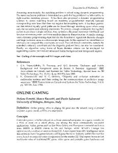
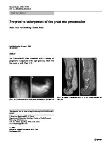
(V~ - 1) and eight triangular faces normal to the (111) directions at a distance from the origin of ( 1 / V ~ ) To comply with the fact that the normal direction is perpendicular to the rolling direction, we change the headings in the rolling direction columns of Barrett and Levenson's Table 1 to read "Rolling Direction (R.D.) Degrees from [001], [011], [ 1 i l ] . " The revised individual changes in orientation with respect to the normal direction and rolling direction are shown by stereographic projection in Figure 1. By rewriting the initial and final orientations in vector notation, the respective axes and angles of rotation have been computed and are given here in Table I. Using Rodrigues' formula to combine the vectors RA = [UlVlWl] tan (1/2)wl and lib = [u2v2w2]tan (1/2)w2, we find the following resultant Rodrigues vectors Rc for the respective crystals: Crystal 10-1 10-3 10-4 11-1 11-3 11-4
12-1 13-2 14-1 14-2 15-3 D-2 D-4 D-5 D-6 D-7 D-8 D-13
Rc 0.03 -0.05, 0.04 0.18 0.00, 0.07 -0.21 -0.06, 0.09 -0.39 -0.41, 0,17 0.03 -0.24, -0.06 -0.23 0.26, 0.28 0.00 -0.05, 0.08 -0.39 -0.05, 0.41 -0.2 0.05, 0.05 0.34 0.08, 0.27 -0.10 0.17, 0.09 0.08 0.22, 0.35 0.20 0.13, 0.22 0.10 -0.14, 0.21 -0.05 0.03, 0.13 -0.33 0.05, 0.14 0.05 -0.04, 0,03 0.06 0.00, 0.09
1 n tan - w
2 and for a first rotation represented by RA = na tan (1/2)coa followed by a second rotation represented similarly by liB, the resultant rotation is represented by
o-a
RA+RB--RA • R c =
1 -
RA'Ra
For cubic crystals, the fundamental zone lie all points that, from the origin of R Rodrigues vectors for all possible crystal truncated cube with six octagonal faces crystal axes (x,y,z) at a distance from
(within which space, denote rotations) is a normal to the the origin of
K.H.G. ASHBEE, Ivan Racheff Chair of Excellence, is with the Department of Materials Science and Engineering, University of Tennessee, Knoxville, 'IN 37996-2200. J.P. SARGENT, formerly with the H.H. Wills Physics Laboratory, University of Bristol, Bristol, United Kingdom, is Physicist with the Sowerby Research Center, British Aerospace plc, Bristol, United Kingdom. Manuscript submitted February 16, 1989. METALLURGICAL TRANSACTIONS A
Fig. 1 - Stereographic projection of the rotations of the normal direction (lower right) and rolling direction (upper left), for Barrett and Levenson's m crystals. The corners of the unit triangle are the poles 001,011, and 111. VOLUME 21A, JANUARY 1990--253
Table I.
The Coordinates ul, vl, w~ deg and u2, v2, ~t.'2deg of the Rotation Axes for to~ and to2
Crystal
ui
i; 1
wi
to l
u2
v2
w2
10-1 10-3 10-4 11-1 11-3 11-4 12-1 13-2 14-1 14-2 15-3 D-2 D-4 D-5 D-6 D-7 D-8 D-13
0.07 -0.03 0.01 0.66 -0.51 -0.53 -0.02 -0.62 -0.62 0.13 -0.32 -0.24 -0.05 0.01 0.00 -0.04 0.56 0.20
-0.88 -0.31 -0.75 -0.76 0.51 0.53 -0.64 0.39 0.25 -0.78 0.93 0,37 -0.55 -0.42 -0.19 -0.06 -0.82 -0.73
0.47 0.95 0.67 0.01 0.69 0.66 0.76 0.68 0.75 0.62 0.18 0.90 0.83 0.90 0.98 1.00 0.15 0.66
7.7 7.6 12.6 27.3 22.0 25.5 10.5 8.6 1.2 7.6 13.0 20.5 11.1 32.2 10.7 15.1 7.
Data Loading...