Testing the Limits of Small Scale Plasticity with Thin Wires in Torsion
- PDF / 236,981 Bytes
- 5 Pages / 432 x 648 pts Page_size
- 99 Downloads / 308 Views
Testing the Limits of Small Scale Plasticity with Thin Wires in Torsion Andrew J. Bushby1, Julien Feuvrier2, Dong V. Dong1 and David J. Dunstan2 1
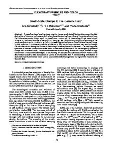
School of Engineering and Materials Science, Queen Mary University of London, London E1 4NS, United Kingdom. 2 School of Physics and Astronomy, Queen Mary University of London, London E1 4NS, United Kingdom. ABSTRACT Torsion experiments on 50μm diameter Cu wires are reported, using the load/unload method and a gauge length of 1m to obtain torsional strain sensitivity better than unity microstrain. The experiments are able to resolve reversible and irreversible deformation at such very low strains. Plastic deformation, dislocation creep and the Bauschinger effect are easily observed at room temperature and at about 300°C, both in the low-strain regime where it is unlikely that dislocation sources are activated, and at higher plastic strain. INTRODUCTION Many experiments in small scale plasticity focus on the use of small sized specimens. These are often prepared by focused ion-beam milling, and studied by mechanical testing in situ in electron microscopes. However, studying thin wires (10μm - 100μm diameter) in torsion and using macroscopic gauge lengths up to 1m has the advantage of giving very high strain resolution and so can explore the very early stages of plasticity.[1, 2] Such data may be relevant to understanding macroscopic plasticity, creep and fatigue as well to understanding the size effect in small scale plasticity. Here we show data obtained from 50μm diameter Cu wires under torsion at room temperature and at 300° C. Microplasticity in both forward and reverse loading is observed. Dislocation creep and the Bauschinger effect are readily observed. At high temperature, early plasticity is fully reversible simply upon unloading. METHODS The load – unload method is used to avoid the need for any direct form of stress or torque measurement. The principle is shown in Fig.1, and the apparatus is described in detail in Ref.3. Briefly, the wire under test, of radius a and test length L, is hung vertically with a crossbar fixed at the bottom. A pair of pins engage with the crossbar to twist the wire to given load angles ϕL. On untwisting, when the pins disengage the unload angle ϕU is measured. The load angle determines the total torsion, which may be expressed as the surface strain εS equal to the torsion θS = ϕL a/L. The unload angle determines the plastic torsion, θpl = ϕU a/L. The elastic torsion may be determined by θel + θpl = θS. The elastic and plastic torsions should not be expressed as elastic and plastic surface strains since that is to make assumptions about the distribution of elastic and plastic strain over the radius.
61
Loading
Unloading
2a
2a
L = 1m
L = 1m
Load angle ϕL
Unload angle ϕU
Surface shear
Plastic torsion
Figure 1. Loading by torsion through a load angle ϕL determines the total surface shear strain θS. Unloading and measuring the unload angle ϕU shows how this divides into elastic torsion θel and plastic torsion θpl. The crossba
Data Loading...