The critical thickness for the formation of Ni-Si-B amorphous alloys
- PDF / 853,182 Bytes
- 5 Pages / 594 x 774 pts Page_size
- 16 Downloads / 264 Views
aim of this paper is to present the outline of the quenching apparatus and the method to estimate the critical sample thickness for the formation of an a m o r p h o u s phase in Ni-Si-B alloys. The second is to investigate the effect of ribbon thickness on the mechanical properties and thermal stability of the a m o r p h o u s alloys. 2. M O D I F I E D M E L T - S P I N N I N G T Y P E QUENCHING APPARATUS Figure 1 shows a schematic illustration of the meltspinning type quenching apparatus which enables the copper roller (20 cm in diam) revolving at high speeds to stop in a very short time. The time (1 to 2 s) required for the roller to stop was chosen so as to eject the molten alloy through a small orifice by argon pressure. As shown in (a), three kinds of brakes of dynamic, magnetic and disk types are attached to the shaft of the copper roller; a rapid stop is achieved by an appropriate combination of the three kinds of brakes. Table I represents the time required for the roller revolving at 2000 or 5000 rpm to stop completely in various combinations of the brakes. It is to be noticed that the roller applied with the dynamic and disk brakes stops in as short a time as 1.5 s even at the speed as high as 5000 rpm. Hence, a stop of the roller in subsequent investigations was carried out only by the simultaneous operation of dynamic and disk brakes. With decreasing rotation speed of the roller, the thickness o f the as-quenched samples increases continuously in the range of a b o u t 30 to 300 /~m, but the width is almost constant (1 to 1.5 ram). It is to be noticed that a continuous ribbon with a variation of thickness as large as about 270/~m is produced in one ejective operation. The uniformity of nozzle geometries was achieved using a ruby tube with constant shape and size. Further, all other quenching parameters, such as impinging stream, ejective pressure and the distance between the roller and the end of a quartz tube, were kept constant. Also, the
ISSN 0360-2133/ 81/0611-1027500.75/0 9 1981 AMERICAN SOCIETY FOR METALS AND THE METALLURGICAL SOCIETY OF AIME
VOLUME 12A, JUNE 1981--1027
6
,I 5
8.33 • 10-2 - 1.33 K/s. Ductility was evaluated by measuring the radius of curvature at fracture in a simple bend test.
3
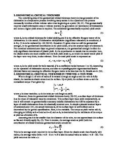
4. RESULTS A N D D I S C U S S I O N 1) Critical Ribbon Thickness for the Formation of A m o r p h o u s Single Phase in Ni-Si-B Alloys (a) (b) Fig. l--(a) Schematic illustration of the modified meh-quenchmg apparatus used in the present work, and enlarged illustraion (b) of the region marked with open circle in (a). 1) Motor, 2) dynamic brake, 3) copper roller, 4) clutch and magnetic brake, 5) disk brake, 6) argon gas, 7) electric furnace, 8) thermocouple, 9) molten alloy, 10) ruby nozzle (0.Statue'), 11) ribbon specimen.
melt was ejected from a temperature about 75 K above the liquidus temperature. 3. E X P E R I M E N T A L P R O C E D U R E S Alloys used in the present work are of the Ni-Si-B ternary system. The parent alloys were melted under a protective argon atmosphere in an induction
Data Loading...