The noncontinuum crack tip deformation behavior of surface microcracks
- PDF / 1,376,254 Bytes
- 7 Pages / 594 x 774 pts Page_size
- 66 Downloads / 383 Views
Fe, 0.2 Mn, balance A1. Flexural fatigue specimens 7 were fabricated from a 3.8 cm thick plate and were oriented so that the applied stress axis was parallel to the rolling direction. To minimize residual surface stress, the final machining proceeded with decreasing cutting depth ending with a series of 5 cuts removing 20/~m per pass. Subsequently, the specimens were polished using 0.03 ~m AI203 powder. The specimens were fatigued in air in deflection controlled cantilever bending, and were then transferred to a scanning electron microscope for characterization. Specimens were loaded in situ to the desired tensile surface stress using a jig described elsewhere. 7 During fatigue all loads were fully reversed with a constant maximum cyclic stress amplitude in the range of 0.8 to 0.9 of the yield strength (O'yield ~ 350 MN/m2). Tests were terminated when the largest surface crack on a specimen was approximately 500 ~tm in length. Cracks nucleate principally from intermetallic particles near the surface in the A1 2219-T815 alloy investigated. Occasionally, grain boundary cracking is observed. Pure crystallographic cracking in regions of persistent slip is rare. Mode I (Stage II) propagation of microcracks nucleated at constituent particles is common, especially for cracks that have propagated beyond the grain of nucleation. In the present investigation, measurements were confined to selected cracks for which the preponderance of propagation was in Mode I. Cracks studied typically nucleated at intermetallics and propagated past the grain of nucleation. The measurements made were for crack lengths in the range of 30 to 155/~m. RESULTS Results are presented of three types of measurements made to characterize the crack tip deformation behavior unique to microcracks. They illustrate the noncontinuum nature of deformation observed for cracks of approximately grain size in length. The measurements show that: A) crack tip closure stress can be anisotropic, with large closure stress characteristically associated with a tip just beginning to propagate into a large grain; B) cracks having a large closure stress have large values of CTOD at the surface tips; C) the CTOD of crack tips is largest when the tip is in a large grain, and
ISSN 0360-2133/80/0711-1117500.75/0 METALLURGICAL TRANSACTIONS A 9 1980 AMERICAN SOCIETY FOR METALS AND THE METALLURGICAL SOCIETY OF AIME
VOLUME 11A, JULY 1980--1117
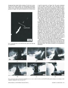
that the plastic c o m p o n e n t of C T O D is insensitive to crack length. Thus, the C T O D , the distance of a crack tip to the next grain b o u n d a r y in the direction of propagation, and the closure stress at the crack tip are intimately related. It will be argued later that the point of c o m m o n a l t y is the plastic zone size, which is determined by the size of the grain at the crack tip. A. Crack Closure Stress Measurements The microcrack shown in Fig. 1 is from a specimen polished as described above, given a light chemical etch to reveal the grain boundaries, and then fatigued at areax -~ 0.87Oyield for 9,500 cycles. I
Data Loading...