Thin Microcrystalline Silicon by a Microwave Remote Plasma Deposition Scheme for Heterojunction Solar Cells and Thin Fil
- PDF / 409,355 Bytes
- 6 Pages / 414.72 x 648 pts Page_size
- 63 Downloads / 288 Views
Society
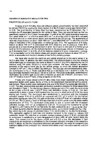
experiments to relate the H2 content and binding to some of the observed electrical properties in these films. Experimental The schematic of the deposition system is shown in Fig. 1. The system comprises of a Pyrex cross, mated to a quartz tube within a resonant cavity. The magnetron tube (of a commercial microwave oven) is mounted on the cavity, which is a rectangular Al waveguide. The modified power supply is controlled by a variac so that the input power can be continuously varied up to 1000 W. The plasma is excited in a background gas in the quartz tube and the process gases are fed at the front end of the quartz tube. The two permanent magnets (885 Gauss) provide the ECR condition. A 2" stainless steel block with heater and thermocouple serves as the substrate holder. The chamber is pumped by a diffusion pump, and has a base pressure of < 10-6 Torr. A cold trap is used to reduce backstreaming. The probe measurements were conducted using a 1 mm diameter wire with 1 cm of exposed length with the rest being insulated. The collected current by the probe was measured for H2 , He, and Ar discharges for normal operating conditions of pressure and power. Microcrystalline silicon was deposited on Coming glass and oxidized wafer at 10-15 mTorr pressures for various growth conditions. Microstructural changes in the film were studied by Raman measurements at the Ar 5145 A line on the films deposited on glass substrates. Al contacts 1mm square spaced 40 gm apart were evaporated for conductivity measurements and the photoconductivity was evaluated at a illumination of 100 mW/cm 2 . Hydrogen content and evolution profile in the samples was studied by heating the film deposited on oxidized wafer in a vacuum at a constant rate of 20 'C/s while measuring the partial pressure of H2 ' ions with a quadrupole mass spectrometer. Substrate Holder
.Power
S .,
Magnetron Gun
... ..... ........-
Quartz Tube
F
SGae
Supply
Resonant Cavity Magnet Gas Feed Tube
Diffusion pump
Fig. I Schematic of the plasma deposition system
Results The probes to evaluate the plasma were placed about 14 cm away from the magnets, downstream in the plasma, to avoid the magnetic field effects on the collected current. Fig.2 shows the electron current for a H2 discharge operating at two conditions, one for 400 W at a pressure of 10 mTorr, and another for a condition of higher power and lower pressure. Electron
902
density (ne), electron temperatures (Te), and plasma potential (Vp) are some of the parameters that are extracted from this curve. Simple probe theory to estimate these parameters assumes that the electrons in the plasma are Maxwellian distributions [8]. The collected current is defined as I=Ik*exp(-qV/kTe), where L*is the electron saturation current, also I*=Aqn0 Te / 2 1Tne , where me is the mass of an electron and A is the probe area. For the 10 mTorr discharge, Te was 12.5 eV, and the electron density estimated from this was about 2x10 8cm-3 with a Vp of 18 volts. The collected current is seen to increase with decreasing pre
Data Loading...