X-ray-line-profile analysis of titanium alloys
- PDF / 508,054 Bytes
- 4 Pages / 612 x 792 pts (letter) Page_size
- 51 Downloads / 297 Views
TRANSACTIONS A
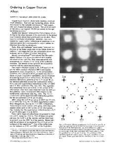
An investigation into the changes of stacking fault energy ~ with increasing solute concentration in the binary Ti-A1 alloy system appeared to be a logical and promising starting p o i n t . Usually ~ is determined through transmission electron microscopy m e a s u r e ments of extended nodes, of fault pairs, of d i r e c t resolution of dissociated dislocations u s i n g weak beam techniques, and of stacking fault tetrahedra. However, in pure T i the nodes are not extended, the inference b e i n g that T is too high t o be measured directly. Other techniques for measuring V indirectly include X - r a y line broadening, TIII mechanical m e a s urements, texture measurements, and measurement of quenched stacking fault tetrahedra. Of these techniques the most promising and straightforward method is X-ray-line-broadening analysis, in which a quantity (the stacking fault probability) inversely proportional t o ~ can be deduced. X-ray-line-broadening analysis is based on the spreading of the diffraction line due t o s e v e r e deformation of the specimen. This broadening is compared t o the instrumental broadening obtained by the diffraction from a well-annealed powder. Fig. 1 depicts the broadening of the (1011) line for two alloys as compared t o instrumental broadening. The resulting broadening can then be interpreted in t e r m s of the microstrain, domain size, and stacking faults that occurred as a result of dislocation interactions during the deformation process. T h e s e data can be complemented by transmission electron microscopy of both annealed and slightly deformed alloys. X-RAY-LINE-BROADENING
MEASUREMENTS
The alloys were prepared for X - r a y diffraction by filing at room temperature, collecting the resulting s m a l l m e t a l particles, and then sifting these particles through a No. 325 mesh sieve. The resulting powder was placed in a specimen holder using a dilute solution of collodion in amylacetate as a binder. X - r a y line profiles of the (10il), (10i2), and (1013) fault-affected reflections, as well as the (10i0), (0002), (119.0), and (0004) fault-unaffected reflections were recorded. The incident radiation was CuKc~; a nickel filter and both current and voltage regulators were employed. The diffracted intensities were i n c i dent on a LiF curved-crystal monochromator, then detected by a proportional counter; the resulting signal was amplified and processed through a pulseheight analyzer. The r e g i o n 26 deg < 20 < 90 deg was step-scanned for a preset time of 100 s at s t e p s of VOLUME 8A, FEBRUARY 1977-279
then used t o determine the distortion coefficients for a Gaussian s t r a i n distribution.
( [OTi )PEAK
T I ( AN~NEALED ) 2 where is the mean-square microstrain in the crystal. The size coefficients A s for fault-affected r e f l e c tions, having been corrected for strain broadening by the use of the distortion coefficients, include effects a r i s i n g from particle size and faulting. The deformation fault probability ~, the growth fault probability/3, and t
Data Loading...