Bi-Directional Motion Achieved with a Surface Micromachined Electrothermal MEMS Microengine
- PDF / 1,005,535 Bytes
- 6 Pages / 612 x 792 pts (letter) Page_size
- 98 Downloads / 295 Views
D11.7.1
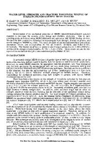
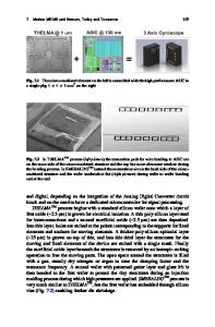
Bi-Directional Motion Achieved with a Surface Micromachined Electrothermal MEMS Microengine Edward Kolesar, Alfred Jayachandran, William Odom, Matthew Ruff, Justin McAllister, Simon Ko, Jeffrey Howard, Peter Allen, Richard Wilks, Josh Wilken, Noah Boydston and Jorge Bosch Texas Christian University, Department of Engineering, Fort Worth, TX 76129 U.S.A. ABSTRACT This research is focused on the design and experimental characterization of an electrothermal microengine that is capable of bi-directional motion. The microengine has been operated to control the position a linear shuttle and rotate a set of gears. INTRODUCTION The seamless integration of conventional microelectronics with three-dimensional, microdynamic, mechanical components can readily be accomplished using microelectromechanical systems (MEMS) technology. Numerous electrically driven microactuators have been investigated for positioning individual elements in microelectromechanical systems (MEMS). The most common modes of actuation are electrostatic, magnetostatic, piezoelectric and thermal expansion [1]. Unfortunately, the forces produced by electrostatic and magnetostatic actuators tend to be small, and to achieve large displacements, it is necessary to either apply a large voltage or operate the devices in a resonant mode. On the other hand, piezoelectric and thermal expansion actuators can be configured to produce large forces and large displacements. Unfortunately, piezoelectric materials are not routinely supported in the fabrication processes offered by commercial MEMS foundries. As a result, these limitations have focused attention on thermally-actuated devices for generating large forces and displacements [2]. This research is focused on incorporating the MEMS electrothermal microactuator device whose design and performance has been documented by the authors in an earlier publication [3]. The MEMS polysilicon electrothermal microactuator depicted in Figure 1 uses resistive (Joule) heating to generate thermal expansion and movement. When current is passed through the actuator from anchor-to-anchor, the larger current density in the narrower “hot” arm causes it to heat and expand along its length more than the “cold” arm. Since both arms are joined at their free (released) ends, the difference in length of the two arms causes the microactuator tip to move in an arc-like counter-clockwise pattern about the flexure element incorporated at the anchor end of the “cold” arm. Removing the current from the device allows it to return to its equilibrium state. DESIGN AND FABRICATION The design of the electrothermal microactuator microengine was accomplished with the MEMSPro® CAD software program [4], and the devices were fabricated using the PolyMUMPs foundry service [5]. The PolyMUMPs material system and a detailed tutorial describing the associated MEMS fabrication process are described on the MEMSCAP web site [5]. To
D11.7.2
minimize stiction problems that are commonly associated with the wet chemical sacrificial glass release etch process,
Data Loading...