Compound Semiconductor Applications for Automotive Sensors
- PDF / 868,742 Bytes
- 12 Pages / 418.68 x 637.2 pts Page_size
- 102 Downloads / 495 Views
VH,
appears
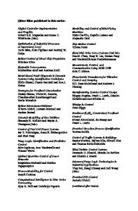
at two voltage contacts, separate from the driving contacts and is given by VH = IB / (net), where I is the current through the device, B is the applied magnetic field, n is the carrier concentration, t is the thickness of the semiconductor layer and e is the electron charge. Using the expression for the device resistance, we can write VH in terms of the driving voltage, Vi, , as VH = Vin . (W/L) whereby g. is the material mobility, W is the width of the Hall device and L its effective electric length. Since for InSb, as we will discuss, the density n displays a sharper temperature dependence than the mobility g., a constant voltage rather than a constant current is often used to drive the Hall sensor. In the former case, the output signal VH is proportional to g.. In the constant current drive case, although g. does not appear directly in the expression for VH, mobility is still the dominant factor determining the signal-to-noise ratio [3]. The second geometry, magnetoresistor, is depicted in Fig. 1(b). Unlike Hall devices, magnetoresistors are nearly always utilized as two-terminal devices. The current path is very short compared to Hall devices, and the very short path, together with the wide current contacts, hinders the development of a transverse Hall voltage. Instead, the device resistance displays a quadratic dependence on magnetic field: R = R0 (I+g(p.B) 2), where Ro is the zero-field resistance at a given temperature, and g is a geometrical factor (g - 0.8). Thus, the magnetic field dependence is once more determined by the mobility p. of the material. Obviously, in either geometry, p. determines the usefulness of a given material for magnetic sensing applications. Moreover, in the case of epitaxial material, this mobility should be achieved with as thin an 65 Mat. Res. Soc. Symp. Proc. Vol. 607 @2000 Materials Research Society
b) R
Ohmic metal Semiconductor
Figure 1: Semiconductor magnetic sensor geometries: a) Hall geometry (4-contact), illustrated under constant driving voltage (Vi') conditions, and b) magnetoresistor geometry (2-contact), illustrated as a resistance measurement (practical magnetoresistorsare composed of a series combination of such elements). active region as possible to increase the device resistance and thus minimize current and power consumption. Most of the work described here has focused on achieving these contradictory dictates on InSb. Materials often encountered in magnetic sensor applications are Si, GaAs, InAs and InSb, in order of increasing p.. Si, always used in the Hall geometry, enjoys the advantage of very mature processing technology but, when used as a magnetic sensor, suffers considerable disadvantages because of its low mobility, and its sensitivity to piezo-electrically induced offsets [1, 4]. Cancellation of these effects necessitates the use of complex multiple-plate Hall geometries, whereas the low pt translates to low sensitivity, requiring substantial on-chip amplification and other signal processing [4]. Thus, Si Hall plates are almost alwa
Data Loading...