Computer modeling of the jump-like deformation of AMg6 alloy
- PDF / 342,673 Bytes
- 6 Pages / 595.276 x 793.701 pts Page_size
- 101 Downloads / 267 Views
COMPUTER MODELING OF THE JUMP-LIKE DEFORMATION OF AMg6 ALLOY P. V. Yasnii, Yu. I. Pyndus, V. B. Hlad’o, and I. V. Shul’han
UDC 539.3
We describe a procedure for modeling the structural inhomogeneity of a material by the finite element method. We consider the material as a composite consisting of an elastoplastic matrix and brittle inclusions (dispersoids). The finite element model is based on experimental data on the concentration of inclusions and their geometrical sizes. The proposed finite element model describes well the jump-like deformation of AMg6 alloy.
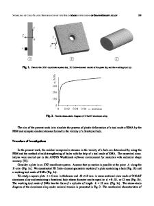
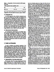
In the tensile stress-strain diagrams of some materials, there appear strain jumps [1 – 4]. In particular, such jumps were detected in the course of tension of AMg6 alloy with the destruction of disperse inclusions of the secondary phase depending on their size and distribution [5]. In the present work, we describe a procedure for modeling the influence of structural components on the deformation of AMg6 alloy with the help of the ANSYS program package, based on the finite element method (FEM). Microstructural Investigations In the tensile stress-strain diagram of smooth cylindrical specimens at a temperature of 20°C, there appear strain jumps due to the cracking of disperse inclusions of the secondary phase and scattering of dislocation clouds [5]. We studied the number of disperse inclusions in the cross section of specimens and their cracking after plastic deformation in the longitudinal direction by the method of transmission electron microscopy of thin foils on a PEM-125K microscope. The dispersoids of length from 0.2 to 5 μm and diameter from 0.08 to 0.15 μm were stretched in the direction of forge-rolling. Their number in the matrix of the α-solid solution of Mg in Al in cross section is about 3 × 10⁶ / mm2 (Fig. 1a) [5]. After stretching in the longitudinal direction, the dispersoids crack (Fig. 1b) into 2 – 7 fragments depending on the initial form factor α (the ratio between the length and width of an inclusion) till it reaches a value of 3.4. The dispersoids with initial α ≤ 3.4 are not destroyed. Modeling by the Finite Element Method Our computations by this method were carried out with the help of the ANSYS program package, version 9.0. The computational model was based on experimental data on the number of inclusions according to the histograms of their distribution depending on the initial form factor [5]. The number of inclusions in the model was n = 100. According to experimental data, for the cross section area S2 = 10– 8 m2, the total area of inclusions is S1 = 5.42 ⋅ 10– 10 m2. We assumed the following: Pulyui Ternopil’ State Technical University, Ternopil’, Ukraine. Translated from Fizyko-Khimichna Mekhanika Materialiv, Vol. 44, No. 1, pp. 41 – 44, January – February, 2008. Original article submitted July 10, 2007. 1068–820X/08/4401–0043
© 2008
Springer Science+Business Media, Inc.
43
44
P. V. Y ASNII, YU. I. PYNDUS , V. B. HLAD’O,
AND
I. V. SHUL’HAN
Fig. 1. Microstructure of AMg6 alloy: disperse inclusions in the cross secti
Data Loading...