Contact Pressure in Honing
- PDF / 406,236 Bytes
- 3 Pages / 612 x 792 pts (letter) Page_size
- 89 Downloads / 355 Views
act Pressure in Honing K. R. Muratova, *, T. R. Ablyaza, and E. A. Gasheva aPerm
National Research Polytechnic University, Perm, Russia *e-mail: [email protected]
Received January 22, 2020; revised January 22, 2020; accepted January 22, 2020
Abstract—Contact in the honing of cylindrical holes is simulated. Nonlinear behavior of the mean contact pressure and the transfer coefficient is observed. These factors depend on the applied force and the surface relief, as well as the materials used in the tool and workpiece. Keywords: honing, contact problem, macroscopic relief, transfer coefficient DOI: 10.3103/S1068798X20100160
When the expansion cone moves, load F is applied to the workpiece. That produces elastic strain in the workpiece and the tool (the honing head). By considering the contact of the toric surface with the cylindrical tool surface, we may clarify the overall behavior in honing. SolidWorks Simulation software is used to model the workpiece–tool contact [2]. The workpiece consists of steel, and the tool of bronze. The contact load is specified by the mutual penetration of the workpiece and the tool (tight fit). The height of the circular segment is related to the chord and radius of the circle as follows (Fig. 1a)
Н =
2 D1 D2 − 1 −L, 2 4 4
(1)
where L is the chord of the circle; D1 = D + 2δ.
859
(b)
D D1 R1
1
D1
R2
δ
R1
H
d
H
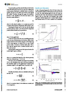
The longitudinal and transverse deviation δ of the hole contour may be simulated by means of a set of toric surfaces at the surface of the ideal hole D1 (Fig. 1a). The transverse profile of the toric surface corresponds to an arc of radius R1, and the longitudinal profile to an arc of radius R2 (Fig. 1b).
(a)
δ
In honing, hole surfaces are machined by a set of interconnected abrasive or diamond bars mounted in a tool head, as a result of kinematic contact [1]. The general features of hole honing resemble those of the abrasive finishing of planes: (1) large contact area of the tool and workpiece; (2) simultaneous action of numerous cutting grains (with a specific height distribution and different shapes) on the machined surface; (3) complex trajectories of the cutting grains at relatively low speeds; (4) low temperature in the machining zone, with no phase transitions or structural changes at the workpiece surface. In honing, the force is distributed nonuniformly among the individual grains. The force experienced by each grain depends on how far it projects from the binder (beyond some mean level) and may vary from the limiting value (when the grain is wrenched from the binder) to zero. Quantitative assessment of the forces in honing entails knowledge of how the contact pressure depends on the geometry of the machined surface and the mechanical properties of the material. The contact pressure is understood to be the mean (over the area) of the total pressure from the set of incompressible abrasive grains at the workpiece–tool contact spot.
Fig. 1. Simulation of the longitudinal (a) and transverse (b) hole profile.
860
MURATOV et al.
(a)
(b)
(c) R2 δ
R1
T
Data Loading...