Effects of Creep and Thermal Drift on Modulus Measurement Using Depth-sensing Indentation
- PDF / 347,885 Bytes
- 9 Pages / 612 x 792 pts (letter) Page_size
- 76 Downloads / 452 Views
In modulus measurement by depth-sensing indentation, previous considerations assume elastic recovery to be the sole process during unloading, but in reality creep and thermal drift may also occur, causing serious errors in the measured modulus. In this work, the problem of indentation on a linear viscoelastic half-space is solved using the correspondence principle between elasticity and linear viscoelasticity. The correction term due to creep in the apparent contact compliance is found to be equal to the ratio of the indenter displacement rate at the end of the load hold to the unloading rate. A condition for nullifying the effect of thermal drift on modulus measurement is also proposed. With this condition satisfied, the effect of thermal drift on the calculated modulus is negligible irrespective of the magnitude of the drift rate.
I. INTRODUCTION
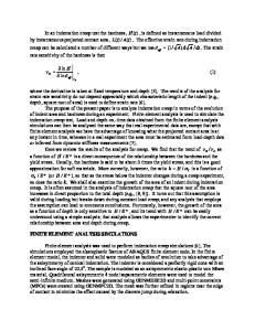
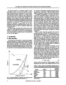
Depth-sensing indentation is rapidly becoming a standard method for measuring the elastic modulus of materials.1– 6 In the Oliver–Pharr scheme,4 the elastic modulus of the specimen is estimated from the unloading segment of the load–displacement curve in which the material is assumed to undergo purely elastic recovery. However, even for metals at room temperature, creep effects may be significant at the peak load. Examples to illustrate this are shown in Fig. 1, which shows the displacement–time curves of aluminium and Ni3Al samples during load hold at the peak load. It can be seen that the indenter displacement continues to increase in both cases, even after a long hold of 10 min, and that the displacement rate appears to settle to a steady value of approximately 0.02 nm/s in Al and 0.009 nm/s in Ni3Al. Such a significant creep effect at the peak load may influence the subsequent unloading behavior, especially when the unloading rate is slow. In the extreme case of creep dominating elastic recovery at the onset of unload, the load–displacement curve may even exhibit a “nose.” An example of this is shown in Fig. 2 for aluminium. Figure 2(a) shows load schedules (i) to (iii) for three similar indentation experiments on the same aluminium sample. Load schedule (i) has a very rapid unloading rate, while (ii) and (iii) have a common but slower unloading rate. Schedules (i) and (ii) have a short load hold before unload, while (iii) has a longer load hold. The unloading curves for the three schedules are shown in Fig. 2(b). A conspicuous nose can be seen in the unloading curve for (ii). It can be seen that the nose disappears when the unloading rate is increased [c.f. (i)] or when the 660
http://journals.cambridge.org
J. Mater. Res., Vol. 17, No. 3, Mar 2002 Downloaded: 07 Feb 2015
load hold before unload is lengthened [c.f. (iii)]. When a nose appears, the elastic modulus cannot be calculated accurately using the Oliver–Pharr scheme, since the apparent contact stiffness is now negative. Even when a nose does not occur, the presence of creep may load to serious errors in the estimation of the modulus, unless one corrects for its effect. In this paper, we present a simple sc
Data Loading...