Effects of Interface Intermixing on the Magnetoresistance of Spin Valves with Uncoupled Co-Layers
- PDF / 1,068,243 Bytes
- 6 Pages / 414.72 x 648 pts Page_size
- 103 Downloads / 337 Views
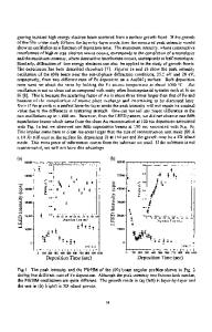
between M, and M2 which causes an antiparallel alignment between M2 and the other Co-layers at small applied fields. The thickness of the Cu-layer is chosen such that this layer decouples M 2 and M3. The samples are HV-magnetron sputter deposited on SiO 2 substrates at room temperature and an Ar-pressure of 7 mTorr. The intermixed region of CoCu at the Cu/M 3 interface is introduced by alternately depositing 1A Co and 1A Cu. The nominal thickness, t, of this intermixed region varies from 0 to 36A. In some cases this intermixed region was divided into two regions of thickness t/2, one at the M2/Cu interface and one at the Cu/M 3 interface. The type II samples are exchange biased spin valves which are DC magnetron sputtered on Si(100) substrates at room temperature. They consist of 3oATa/(ioo-t/4)ACo/(t/2)ACoCu/(40-t/2)ACu/(t/2)A CoCu/(50-t/4)ACo/IOOAFeMn/3OATa. Again the thickness of the Cu spacer is such that the 100A Colayer is not coupled to the 50A Co-layer. The magnetization direction of the 50A Co-layer is pinned in a certain direction through direct exchange coupling to the antiferromagnetic FeMn-layer. In these samples the nominal thickness of the total intermixed CoCu-region, t, varies from 0 to 30A. The CoCu-regions in these samples were deposited by co-sputtering of Co and Cu. To vary the intrinsic initial intermixing two series were grown in which the Co/CoCu/Cu/CoCu/Co-stack was deposited at Ar-pressures of 5 and 10 mTorr. All other layers are grown at an Ar-pressure of 5 mTorr. SAMPLE CHARACTERIZATION To characterize the samples magnetization measurements were performed. In Fig. IA a typical magnetization loop is shown for the type I samples. As layer M3 is not coupled to the other magnetic layers, the magnetization of this layer will always point in the direction of the field. Layers M, and M2 are coupled strongly antiferromagnetically and therefore at small fields (< HI) the magnetization directions of these layers will align antiparallel with the magnetization direction of the thinner layer, M2, pointing opposite to the field direction. Note that now also the magnetization directions of layers M 2 and M 3 are aligned antiparallel although they are not coupled to each other. When the field is increased, the magnetiza-
- - -
1.0
1.0 -
100 FeMn
0.5
Hi
0.5 50 Co
10~~
cý 0
,
..... 4dCu
100c 0
0.o0.0 25 Co 7'3Co-
M2 M1•
-0.5
-0.5
-1.0 ••,
-1.0
*
-.
-0.5
0.0
0.5
1.0
Field (1)
Field (M)
Fig. 1: Typical M(H)-loopsforA) type I samples andB) type I1 samples. The arrows indicate the magnetization directionsof the Co-layers. 392
tion direction of layer M 2 will gradually reverse to the field direction until saturation is reached at H=H2 . In Fig. lB a typical magnetization loop of a type II sample is shown. In fact the measurement shows two hysteresis loops. One around H=0 T for the "free" Co-layer and one around the exchange biasing field H, for the exchange-biased Co-layer. Between H=0 T and H=I-L a region exists of complete antiparallel alignment. The most essential feature of bo
Data Loading...