Fatigue threshold and low-rate crack propagation properties for structural steels in 3 Pct sodium chloride aqueous solut
- PDF / 2,462,299 Bytes
- 11 Pages / 594 x 774 pts Page_size
- 84 Downloads / 297 Views
I.
INTRODUCTION
IN corrosive environments, fatigue life is dominated by crack propagation, because cracks initiate early at pits.t~l Therefore, near-threshold fatigue crack propagation properties in corrosive environments are of practical importance in the design of machines and structures. In this study, the fatigue threshold and low-rate crack propagation properties of five steels are investigated under freely corroding and cathodically protected conditions in a 3 pct NaC1 aqueous solution. The estimation of crack closure is difficult in corrosive environments, because closure is induced by the hydrodynamic wedging of the solution, t2,3,41Therefore, a new AK-decreasing method, [5,6] where minimum load is increased with crack extension while maintaining maximum load constant, is employed in order to avoid closure. The data obtained under closurefree conditions are analyzed in connection with the corrosion reaction of the bare surface produced at the crack tip in each loading cycle. II.
EXPERIMENTAL PROCEDURE
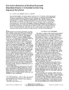
The materials investigated were a carbon steel, $45C, two high-strength steels, SM50B and HT80, and two stainless steels, SUS304 and SUS403. Their chemical compositions are given in Table I, and mechanical properties, heat-treatment conditions, and microstructures are given in Table II. Fatigue crack propagation tests were conducted with a small compact tension (CT) specimen of 25-mm width and 5-mm thickness (Figure 1) in a 150 kN servohydraulic-
SABURO MATSUOKA, Head, and HIROYUKI MASUDA, Senior Researcher, are with the Environmental Performance Division, and MASUO SHIMODAIRA, Researcher, is with the Failure Physics Division, National Research Institute for Metals, 2-3-12 Nakameguro, Meguro-ku, Tokyo 153, Japan. Manuscript submitted March 29, 1989. METALLURGICAL TRANSACTIONS A
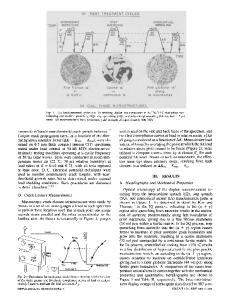
type machine. A special device was used to obtain a load suitable for the small CT specimen, t71 The load applied to the specimen was measured by a load cell of 3 kN in the device and sent to the control circuit in the machine. Two AK-decreasing tests were carried out in a sinusoidal load-wave pattern at frequencies of 0.3 and 30 Hz (Figures 2(a) and (b)). One was a new test wherein minimum load, Pmin, w a s increased with increasing crack length, a, while maximum load, Pm~x, remained constant. [5] This was termed the "Pin,x-COnstant AK-decreasing test." The other was the more usual test wherein the load ratio, R = Pmin/Pm~x, was kept constant at a value of 0.7. This was termed the "R-constant AK-decreasing test." The AK-decreasing rate, d ( A K ) / d a , was - 2 GPa m -1/z for both tests. The Pma~-Constant AK-decreasing test was started at R > 0.5 and AK > 6 MPa m I/z to avoid crack closure down to the threshold. The constant-amplitude loading test, where AK was increased with increasing crack length, was also conducted at frequencies between 0.03 and 30 Hz at load ratios higher than 0.6. This was termed the "AP-constant AK-increasing test. A computer system t51was installed for data acquisition and machine control. A 2-mm-long a
Data Loading...