Fracture Tests of Polysilicon Film
- PDF / 1,448,256 Bytes
- 6 Pages / 414.72 x 648 pts Page_size
- 77 Downloads / 331 Views
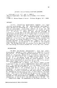
BIAXIAL TEST # 18 1.50
1.25
..... ......... " . ............. . ...............
Axia Lateral Strain Strain 10. 07 ... ......... , .................................. ... .........i .............
It is important to distinguish between fracture stress and fracture T -----...... . .... ....... ...... : .................. ......... .... toughness. The term 'fracture stress' has 05 --- .. .E =169 GPa = 12 0 Pa "been used to denote the maximum stress 0 .2 5 ........... .m..achieved in tests such as shown in Figure 1. 0.00 -0.2 0.0 'Fracture toughness' refers to the load0.2 0.4 0.6 0.8 STRAIN - percent carrying capacity in the presence of a flaw.
S 0.50 U)
51
Mat. Res. Soc. Symp. Proc. Vol. 505 01998 Materials Research Society
There has been one previous measurement of fracture toughness of polysilicon. Kahn et al [4] studied polysilicon films that were relatively thick -- 5 to 7.5 microns. The fracture test structure was essentially a double cantilever beam, i.e. a long rectangular structure with a 2 jtm wide slot extending down the middle of the beam for most of its length. The two beams were pried apart by pushing a 10 jtm diameter probe into the slot and toward its tip. The position of the probe when the structure fractured was measured and used to infer the displacement of the beams. That information, coupled with an elastic finite element analysis of the structure, enabled a determination of the fracture toughness. Sixty-one tests were conducted on both doped and undoped polysilicon with an overall average fracture toughness of 2.3 ± 0.65 MPa-mt/ 2 . Fracture toughness testing, as it has been developed and standardized, requires the loading of a pre-cracked specimen to failure. The maximum load is related to the critical stress intensity
factor, which becomes the fracture toughness if the test conditions are suitable. If the material is ductile, then the crack opening displacement (COD) must be measured to ascertain the applicability of the linear elastic relation between the applied force and the stress intensity factor. The specimen geometry may be fairly simple as for a center-cracked or edge-cracked panel or quite complicated as for a compact tension specimen. It is advantageous if the specimen geometry can be simple, and that is the approach taken here. Wide tensile specimens of polysilicon film with a central slot are tested in this work. The opening displacement across the slot is measured with laser-based interferometry to validate the test procedure. The experimental techniques, including the specimen geometry, the loading mechanism, and COD measurement are presented in the next section. The complete set of results from 12 tests are then presented and discussed. EXPERIMENTAL TECHNIQUES The approach here is to use as simple a geometry and loading system as possible and to also measure the COD during the test. The specimen material and geometry are presented first, followed by a brief description of the laser-based interferometry used to measure the COD. The entire test is run under computer control,
Data Loading...