In Situ Ellipsometry in Microelectronics
- PDF / 2,012,786 Bytes
- 5 Pages / 576 x 777.6 pts Page_size
- 37 Downloads / 358 Views
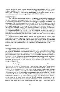
surface, and Figure lb shows multiple reflections at all the material interfaces where additional phase and amplitude changes occur. All changes are in terms of A and ^ and analysis is based on the optical properties of the materials. For a bare reflecting surface the form for A and ^ is as follows: A = Srp — 8 rs and
E.A. Irene and J.A. Woollam
\rj
(1)
with the complex reflection coefficient p given as Introduction Ellipsometry has been used in mi1 croelectronics since the early 1960s when it became necessary to measure the thickness of transparent films on reflective substrates. Ellipsometry is an old technique2 but with the increasing technological importance of thin films, particularly in microelectronics, and with the availability of faster computers for calculations, ellipsometry is in a renaissance. In principle it is a simple technique (don't confuse simple with easy!) that relies primarily on the physical optics of stratified media. Excellent treatments of ellipsometry exist (e.g., a book,3 recent reviews4,5,,), and it is not the intent here to try to improve upon them. Rather, this article is intended to briefly discuss the essential ideas and then to show a few examples of in situ ellipsometry applied to modern materials-research problems. The emphasis here is on in situ ellipsometry, because it is one of the few techniques that can accurately monitor thin-film processes while they occur, yielding both fundamental properties and process information about the system under measurement. In addition it is now possible to use feedback to affect control of thickness, composition, and temperature, for example. We first consider some basic questions: What is ellipsometry, what does it measure, and how well? Next, we discuss hardware for in situ ellipsometry, and finally we show a few examples. What Is Reflection Ellipsometry? Reflection ellipsometry measures changes in polarization of monochromatic light reflecting from matter. Figure la shows linearly polarized monochromatic light propagating from the left (subscript i for incident light and r for reflected) with a single electric vector E, with the field components projected in the plane of the paper Ep, and normal to the plane of the paper £ s . The plane of in-
24
cidence (POI) is formed by the incident and reflected light, and the normal N which is in the plane of the paper in Figure 1. Ep is parallel to the POI and Es is perpendicular. Notice that before reflection the E p and E s components are in phase (for linearly polarized light). In general when polarized monochromatic light reflects from (or transmits through) a surface, both the phase and amplitude change, depending on the optical nature of the material. The quantification of the phase change of Es relative to Ep, A, and the amplitude change V comprise an ellipsometric measurement. Figure la shows reflection ellipsometry at a single
p = tanWexp(/A) = —
where Srp is the phase change for the p component upon reflection and similarly for the s component as 8rs. The Fresnel coefficients are giv
Data Loading...