Insulating and Breakdown Characteristics of Low Temperature GaAs
- PDF / 252,167 Bytes
- 6 Pages / 420.48 x 639 pts Page_size
- 82 Downloads / 311 Views
INSULATING AND BREAKDOWN CHARACTERISTICS OF LOW TEMPERATURE GaAs H. L Grubin, J. P. Kreskovsky and R. Levy Scientific Research Associates, Inc. Glastonbury, Connecticut 06033 ABSTRACT The electrical characteristics of an N(LT)N structure are studied through implementation of numerical simulation techniques for the case of donor traps 0.83 ev below the conduction band and acceptor traps 0.3 ev above the valence band. The results show characteristics sensitive to the relative densities of the traps. In particular, high acceptor trap / low donor trap concentrations generally result in low breakdown voltages, whereas high acceptor / high donor concentrations result in higher breakdown voltages.
INTRODUCTION The purpose of this discussion is to briefly summarize recent calculations of the electrical characteristics of low temperature growth GaAs (LT GaAs). The device studied was a three micron N(LT)N structure with N regions characterized by shallow donors at 101 7 /cmS ; and an LT region characterized by a single level of acceptor traps of density Pat located 0.3 ev above the valence band [1], and a single level of donor traps of density Nd located at 0.83 ev below the conduction band. The results are placed in two categories: Highly resistive LT regions (> 106 ohm-cm) with (a) low current levels and sudden breakdown, and (b) higher current levels with gradual breakdown. Breakdown characteristics depend upon the magnitude and distribution of the field. For high acceptor / low donor trap concentrations the fields is near zero in the LT region and approaches breakdown values at the anode (LT)N interface; for other combinations the field profile is complex. The study suggests that breakdown voltages will depend upon growth and processing temperatures of LT GaAs. THE GOVERNING EQUATIONS The equations include rate equations for electrons and holes, acceptor and donor traps: (1)
a n/l
(2)
a p/0 t + divjp/e) = G + f Cpa[PaPa°- PPa-- + cpd[PdNd + -pNd°I}
(3)
a Pa- /l t =---e2Pa - + e3 Pao
(4)
a Nd +/a t =---e4Nd+ + elNd°
t- div(jn/e) = G + {cndlndNdo-nNd +] + Cna[naPa -- nPal}
Superscripts denote ionized and neutral acceptors and donors; particle currents are: (5)
jn=--e[nvn-Dngradn],
jp = e[pvp-Dpgradp]
and diffusivities are governed by the Einstein relation. Avalanche generation [2] is: (6)
m m G=an 0 exp--(bn/iFj) jJnjl/e + aplexp.-(bp/IFI) llJpl/e
and the emissivity coefficients el...e 4 are: Mat. Res. Soc. Symp. Proc. Vol. 241. 01992 Materials Research Society
40
(7)
em-cndnd + PCpd,
e2 Cnana + PCpa O
e3 cpaPa + ncna,
e4" cpdPd + ncnd
Cnd, cna, etc., are capture coefficients [3]; nd, Pd, etc., are obtained at equilibrium. The above equations are coupled through Poisson's equation, which in terms of energy is: V2 E=-[e22/
(8)
lI(n-p)-(Nd+-Pa-)l
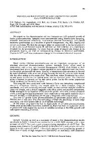
The energy and potential are related, E =--eo; the field in equation (6) is F =-ve. THE RESULTS All calculations were for the figure 1 shallow doping distribution, with the results dependent upon: (i) the Fermi level, (ii) the ratios Pa/Nd, and (iii) the tr
Data Loading...