Measurement of Thin Film Mechanical Properties Using Nanoindentation
- PDF / 1,393,058 Bytes
- 6 Pages / 576 x 777.6 pts Page_size
- 49 Downloads / 482 Views
28
very similar to and contain much the same information as that obtained in a conventional compression test. The major difference in the tests concerns the geometry of the contact between the loading device and the specimen. In a compression test of a cylindrical specimen, the contact area remains essentially constant throughout the test. During loading, the specimen initially deforms elastically and then yields and work hardens, while during unloading, the elastic displacements are recovered. The behavior in a nanoindentation test is inherently different because contact is usually made by a sharp indenter, modeled in Figure 2 as a cone. Because of this, the contact area is initially small, and there is no distinct elastic region at the begin-
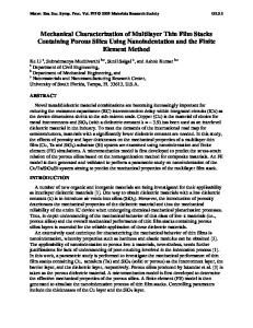
Figure 1. Nanoindentations placed at several selected points in a microelectronic device.
ning of the test; i.e., the deformation has both elastic and plastic displacements from the outset. Furthermore, the contact area continuously changes as the indenter is driven into and withdrawn from the specimen, and these factors complicate the analysis of the data. These problems could be avoided with the use of an indenter with a flat-ended geometry, but such indenters are rarely used in practice for two reasons. First, as mentioned previously, in order to achieve a high degree of spatial resolution, it is usually desirable to make the contact area as small as possible, and this is best accomplished using sharp indenters. Second, it is difficult to assure that the contact between a flat-ended indenter and the specimen is uniform; i.e., due to surface roughness and misalignment of the indenter, contact does not occur uniformly between the specimen and the indenter. For these reasons, the most frequently used indenter in nanoindentation testing is the Berkovich diamond, a threesided pyramidal indenter with the same depth-to-area relation as a Vickers indenter.' The Berkovich indenter is preferred to the Vickers because of the difficulty in grinding the four-sided Vickers to terminate at a point. While the bulk of thin film nanoindentation experiments are like the one described in Figure 2a, other tests are possible when more sophisticated specimens can be prepared. As shown in Figures 2b and 2c, for example, special fabrication techniques can sometimes be used to produce free-standing cantilevered microbeams (Figure 2b) or membranes (Figure 2c). By deflecting these beams and membranes in a nanoindentation system and measuring the resulting load-displacement response, it is possible to measure properties such as the in-plane elastic modulus'" and the residual tensile stress in the film." Note that the nanoindentation system is used to measure loads and displacements in a manner exactly analogous to a conventional mechanical testing system. Several different nanoindentation systems have been designed and at least two are commercially available.11'2" At the heart of each is the ability to produce and measure very small loads and displacements. Load is typically applied either through
Data Loading...