Modeling and Simulation of Pulsed Laser annealing and ablation of Solid Materials
- PDF / 518,661 Bytes
- 6 Pages / 414.72 x 648 pts Page_size
- 54 Downloads / 319 Views
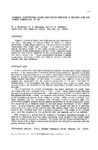
pulsed-laser melting of a-Si at an energy density (Ej) just above the threshold for melting results in a highly undercooled liquid whose formation and subsequent behavior can be studied directly by time-resolved electrical [11,12] and optical [13] measurements. II. Two-dimensional modeling of pulsed-laser interactions with solid materials We divide the sample into contiguous, semi-infinite hexagons as illustrated in Fig. l a. An event is assumed to occur at the center of every hexagon more or less simultaneously across the face of the sample. We have in mind specifically here a nucleation event, but it could also be preferential absorption of the laser pulse at defect sites, positions of macromolecules, etc. Under these conditions, the radial outflow of heat from a given hexagon is exactly balanced by the inflow of heat from the neighboring hexagons. Hexagonal boundary conditions, being difficult to deal with, are replaced as follows. Each hexagon is replaced by an inscribed cylinder and attention is focussed on a single cylinder with the boundary condition that the temperature gradient at the outer wall is zero, as indicated in Fig. lb. This is not expected to introduce significant errors since the amount of material in the interstices is small and is still treated approximately. In applications to nucleation phenomena, we may want to simulate the initial laterally uniform melting of the surface which is then followed by nucleation and growth at sites more or less uniformly distributed across the sample, i.e., at the centers of the hexagons or cylinders. Accordingly, the 2D program was set up so that 1D calculations can be carried out until nucleation of a particular phase has occurred and subsequently 2D calculations are initialized to treat the growth of the newly formed phase in both the x and r directions. The finite difference grid is taken to be layers of certain thibckness in the x direction (typically Ax = 100 A) and rings in the r-direction (Ar = 100 - 200 A). The 2-D heat conduction equation with a source term is given in cylindrical coordinates by aJt
a-axL
DT] +I
axL
ax
a[.Kr aTr + S(x,r,t) r Dr
(1)
rJI
where we have, as in the 1-D case, used Rose's enthalpy formulation [14] of the heat flow problem. Boundary conditions in the x direction are given by T
=0
; Too= Tin
(2)
X=O (a)(b
LASER
.
•
r CONDUCTION
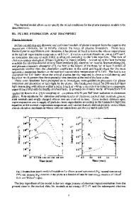
Fig. 1 Geometry for 2D calculations showing (a) the hexagons with inscribed cylinders and (b) the FD cells in the x and r directions for one cylinder. After a certain number of cells of constant size in the x-direction is used, additional cells, each successively doubled in size, are added as needed to satisfy the back boundary condition.
128
and in the r direction by aT
0,
=0
(3)
S(x, r, t) is the source term with the form S(x, r, t) - (1 - R) P(t) a exp(- a x),
(4)
r=o
-T
r-rmax
in which R is the reflectivity of the sample, assumed to be a function of the temperature and phase of the surface, P(t) is the time-dependent intensity of the laser pulse, and cXis the absorption
Data Loading...