An Apparatus for Measuring the Characteristics of the High-Speed Image Converter Cameras Operating in the Range of Soft
- PDF / 2,459,993 Bytes
- 6 Pages / 612 x 792 pts (letter) Page_size
- 19 Downloads / 264 Views
RATORY TECHNIQUES
An Apparatus for Measuring the Characteristics of the High-Speed Image Converter Cameras Operating in the Range of Soft X-Rays and Vacuum UV G. G. Feldmana, V. B. Lebedeva,*, and A. A. Siniichuka a All-Russian
Research Institute for Optical and Physical Measurements, Moscow, 119361 Russia *e-mail: [email protected]
Received March 2, 2020; revised March 13, 2020; accepted March 14, 2020
Abstract—A pumped vacuum apparatus is described that contains an electron gun with an adjustable highvoltage voltage source, interchangeable metal targets, and flanges to which the object under study is connected. The apparatus is especially designed to measure the spatial and temporal characteristics of high-speed image converter streak cameras that operate in the soft X-ray range. It can be used for research and measurements in the design of soft X-ray photodetectors and their main parts, for example, microprobe detectors, imaging devices, solid-state linear and matrix photodetectors, photoemitters operating in vacuum, etc. DOI: 10.1134/S0020441220040247
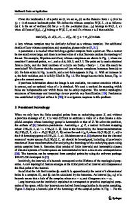
INTRODUCTION High-speed image converter cameras (ICC) [1–3] are designed to measure the spatial and temporal characteristics of optical pulses. In these devices, an electron-optical converter (EOC) with an image scan, which is part of the camera, is used as the primary receiver. The principle of its operation is illustrated in Fig. 1. A measured optical impulse 1 (Fig. 1a), landing on a slot photocathode, excites the flow of photoelectrons 4, which are accelerated towards the luminescent screen 5 and focused on it. When applying the deflec-
tion system 3 synchronously with the optical pulse of a linearly increasing voltage, the electron beam impacts along the surface of the luminescent screen and causes a glow, whose brightness depends on the intensity of the optical pulse at each instant of the scan time (Fig. 1b). The cross section of the beam has a rectangular shape, which, in contrast to the oscilloscope beam, allows one to have two coordinates, that is, temporal and spatial. The spatial coordinate provides information about the distribution of the intensity of the optical pulse along the gap.
(а)
1
B 5
(b)
6
2 3
Δt
4
t
Fig. 1. The principle of operation of the electron-optical converter: (a), time analyzing electron-optical converter (1, input optical pulse; 2, slot photocathode; 3, deflecting system; 4, electron beam; 5, luminescent screen; 6, time scan of the image of the optical pulse); (b), the dependence of the screen brightness B on time t (Δt, the duration of the optical pulse at half maximum).
767
768
FELDMAN et al.
9 10 A1
14
kv1
2 3 4 5
A2
kv2
11 13 16 17
12 18
15 1
22
19 6
R 10 Ω S
21
20 A3
7
8
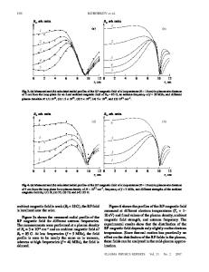
Fig. 2. A diagram of the device. 1, a vacuum chamber; 2, cathode heater; 3, cathode; 4, modulator; 5, anode; 6, target; 7, turbomolecular pump; 8, fore-vacuum pump; 9, cathode heater power supply; 10, adjustable (0–50 kV) cathode power supply 3; 11, modulator control unit 4; 12, focusing coil power supply 13; 14, 15, p
Data Loading...