Fabrication and Optical Pumping of Laser Cavities Made by Cleaving and Wet Chemical Etching
- PDF / 376,456 Bytes
- 6 Pages / 414.72 x 648 pts Page_size
- 112 Downloads / 325 Views
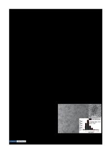
The cleaving process begins with thinning the substrate to 200 pm and polishing the back side. The polished sapphire is lightly scribed into 1-mm-wide sections along the direction using a diamond-tipped scriber. The samples are next mounted using wax to a thin piece of flexible metal, with the epitaxial layers facing the metal. The sample cleaves along the scribe marks into 1-mm-wide bars when the metal piece is bent. The resulting pieces display large areas where the sapphire and epitaxial layers have cleaved cleanly. Because of the 300 rotation of the GaN crystal structure compared to the sapphire crystal structure9 , this surface corresponds to (10 0), or the m-plane, in the sapphire substrate and (1120), or the a-plane, in the epilayers. By examining these regions with an atomic force microscope, vertical striations in the cleaved epilayers were observed, having a roughness of approximately 25 nm. Wet etch rates of 4 nm/s are attained in a 10 % solution of KOH in water by illuminating the GaN with the 325 nm line of a HeCd laser at a power density of 0.06 W/cm2. Titanium is used as an electrical contact and also serves as an etch mask, and carbon is used as a cathode. The roughness of the resulting facets was determined to be approximately 100 nm by scanning electron microscopy. THEORY In order to determine whether the experimental roughness is acceptable, we have developed a model that allows us to determine the maximum allowable roughness in the laser facets that will still allow cavity modes to develop. A laser cavity has discrete allowed modes depending upon the length of the cavity and the index of refraction of the material. Allowed modes are those whose reflections interfere constructively within the cavity. In order to have cavity modes, the mirrors at each end of the cavity must be parallel and smooth. In developing our model, we begin by determining the reflection coefficient at the surfaces. For uncoated surfaces, the Fresnel reflection coefficient can be used: n-1' n+l
(1)
where r is the Fresnel reflection coefficient and n is the index of refraction. broadening per reflection is given by 0b=
2,rnAd 2-- ,
The phase
(2)
where A is the wavelength of interest and Ad is the variance in the length of the cavity caused by roughness, as shown in Fig. 1. A sum over all reflections yields a total phase broadening D = (I - r)• x ,o•(m + 1)r' M=01-
(3)
01-r r)
For constructive interference the total phase broadening should be ;r/2 or less. This condition yields Ad
Data Loading...